|
Massimo Tessitori
|
 |
« Reply #30 on: December 17, 2017, 10:21:15 PM » |
|
Hi Johann, Using the moment to later not be distracted made a lateral view of the three variants of La-5fn. Nice work but, for my eye, the shape of the upper profile of the nose has to be revised: the curve of the front part that I see in photos is more rounded above the division line between front ring and side panels, besides one can see a sharp angle in the front where it starts and is open. But for comparison and LaGG-3, too, the curvature of the wing is noticeable. I fear that this is an impression given by the glossy surface. The outer part of the leading edge reflects the ski and makes a straight light line, but where the wing approaches the fuselage, its dark surface starts to be reflected and its dark reflection on the leading edge is above the light reflection of the ski. If you enlarge the photo, you can see a dark line where the wing reflects the fuselage, and the light reflection of the ski bends downwards. The real profile of the wing includes the dark part above the light line. Regards Massimo |
|
|
|
|
 Logged
|
|
|
|
|
Johann
|
|
« Reply #31 on: December 18, 2017, 06:04:36 AM » |
|
light glare here voobshe at anything. Look at the previous photos from La-5. In the end, there are factory spicifications and there is elementary geometry, in which at three different lengths of the frames of the wing, its front edge simply does not really align in a straight line. This contradicts everything.
By the hood, I understood you, I will once again check this moment
|
|
|
|
|
Logged
|
|
|
|
|
Johann
|
|
« Reply #32 on: December 18, 2017, 07:41:03 AM » |
|
Even in the absence of light glare, a straight line can not be made. Although the visual observation curve is not visible. I do not think that a person's eye can easily catch 2.5 degrees of deviation ...  |
|
|
|
|
Logged
|
|
|
|
|
Massimo Tessitori
|
|
« Reply #33 on: December 18, 2017, 10:27:55 AM » |
|
Hi, on this photo, the change in angulation looks real. It would be good to find other photos to confirm. Finns took some photos of their LaGG-3s from above, I think that an high resolution version could be available. Something like this, maybe in better resolution.  Here I can't see changes in angulation Regards Massimo |
|
|
|
« Last Edit: December 18, 2017, 10:32:07 AM by Massimo Tessitori »
|
Logged
|
|
|
|
|
Johann
|
|
« Reply #34 on: December 18, 2017, 12:19:34 PM » |
|
Hmm ... The same plane, but in a more favorable perspective ... The same wing ... We will impose a vector. There is a discrepancy. Copy the same vectors on the wing from the TO ... Coincides. Put the wing on the photo. And it also co-exists.    Visualization on a photo is not always correct due to distortion not only in perspective, but also can be distorted from exposure, focal length and aperture. This can be confirmed by any professional photographer who worked with old film cameras. BUT in the last series of photos I think convincingly showed the curvature of the wing. And about distortion even on a good photo here is an example. Visually the wing is straight. But we know something with you that this can not be on La-7. Right?  You can independently calculate the curvature of the frames and set them at the zero mark and learn the linearity of the leading edge ... The original can be read separately.  |
|
|
|
|
Logged
|
|
|
|
|
Massimo Tessitori
|
|
« Reply #35 on: December 18, 2017, 06:47:53 PM » |
|
Hi Johann,
I'm very in doubt. On the drawing, the change of angulation is very well visible at naked eye. On photos, I can't see this, and a light curvature can be due to photo distortion. When possible, I've observed even the shadows on the ground, without finding confirmations of changes of angulation in coincidence with the landing gear leg.
Regards
Massimo
|
|
|
|
|
Logged
|
|
|
|
|
Johann
|
|
« Reply #36 on: December 18, 2017, 06:54:32 PM » |
|
That is, even overlaying the drawing on the wing of the photograph is not proof, and all technical descriptions with dimensions and calculations should be thrown into the basket  |
|
|
|
|
Logged
|
|
|
|
|
Massimo Tessitori
|
|
« Reply #37 on: December 18, 2017, 07:11:43 PM » |
|
Hi Johann, if some description says explicitely that the swept angle changed, it is a reliable thing. Another thing is if this conclusion is obtained from drawings without measures of the angle, because by missing the size of a not measured strut they change the angle unwillingly. I've asked Alex Ruckovsky that found this drawing of German origin with measurements of the wing of a LaGG-3: 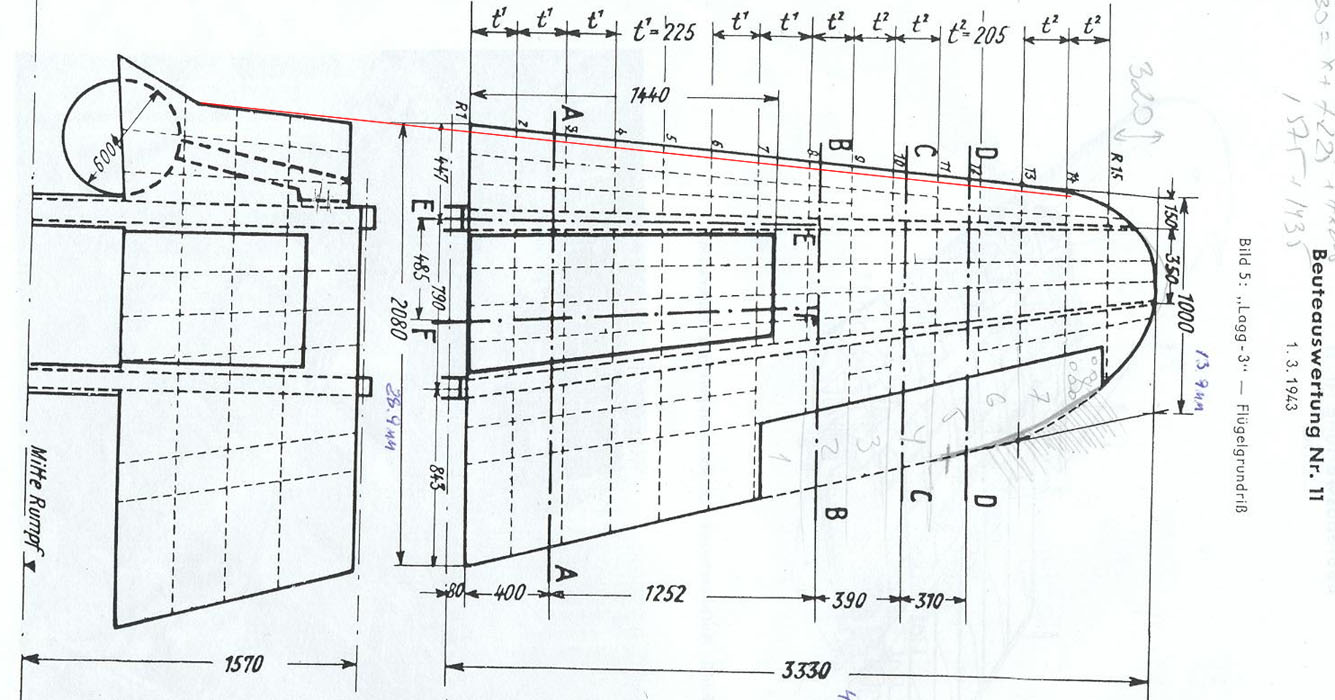 On the base of this drawing, one could deduct that the inner part had a greater sweep angle than the outer one, not smaller. Anyway, the text doesn't say this, nor there are written measurements confirming it, so it is likely a simple error in drawing. Regards Massimo |
|
|
|
|
Logged
|
|
|
|
|
Johann
|
|
« Reply #38 on: December 18, 2017, 07:33:36 PM » |
|
An error in the description of the construction? And in size error? I'm already afraid to fly on them, even a computer game))) Massimo, you can explain - where on your drawings the vector on the wing has the parallelism of the wing edge, and on the centroplane again there is an angle of 2.5 degrees ?  BUT! If even the factory measurements and drawings in the compartment with photos lie, then I see no reason to continue. |
|
|
|
|
Logged
|
|
|
|
|
Johann
|
|
« Reply #39 on: December 18, 2017, 09:20:38 PM » |
|
|
|
|
|
|
Logged
|
|
|
|
|
Massimo Tessitori
|
|
« Reply #40 on: December 18, 2017, 10:09:01 PM » |
|
Hi,
the drawing isn't mine, I have just added a red line that is parallel to the leading edge of the outer console, and ends at the base of the leading edge of the inner part of the wing; this to make clear that the lines are not parallel, but in the opposite way of factory drawings, because seem to show the inner part more swept back. Of course, this characteristic is (probably) not real: they measured the outer console with precision, but not the inner one. Besides I see only linear measurements, not angular ones. At least one angular measurement would have been necessary for a complete work.
The drawing is rotated simply for an error of scanning, but the inner and outer parts are rotated in the same way, so the scan let see that the lines weren't drawn exactly parallel in the original German drawing.
I have not said that measurements lie. Drawings can lie when they are not supported by measurements. When an information is meant, it has to be made intelligible with a quote, note or symbol. If they made a change in angulation well visible inside one drawing, they made it willingly. If the change in angulation results from combining two different drawings, it could be not made willingly and could be the result of a small error in a thing that was not considered important for the ends of that drawing.
If there are other drawings with the exact measurements of the struts inside the inner part of the wing, then it is different because those drawings mean that information as important and exact.
I see that you have drawn two versions of the upper view. At the present state of our knowledges, I think that the brown one is more likely.
Regards
Massimo
|
|
|
|
|
Logged
|
|
|
|
|
Johann
|
|
« Reply #41 on: December 18, 2017, 10:14:58 PM » |
|
While I will use both wing profiles to look for more information. Later it is easier to remove the erroneous than to fix everything on the finished one.
|
|
|
|
|
Logged
|
|
|
|
|
Massimo Tessitori
|
|
« Reply #42 on: December 19, 2017, 07:25:34 AM » |
|
This is wise.
Regards
Massimo
|
|
|
|
|
Logged
|
|
|
|
|
66misos
|
|
« Reply #43 on: December 19, 2017, 08:52:39 AM » |
|
Hi, change in angulation looks here more like on Massimo's red/green marked line drawings:  while here it looks more like on Johann's yellow marked photo:  Regards, 66misos |
|
|
|
|
Logged
|
|
|
|
|
|
|