Though the subject of this build is not a Russian machine, this type was used in quantity by the IRAS, with, I believe, some even surviving into training use into the Soviet period. So with permission from Massimo I am putting up a WIP thread on the build.
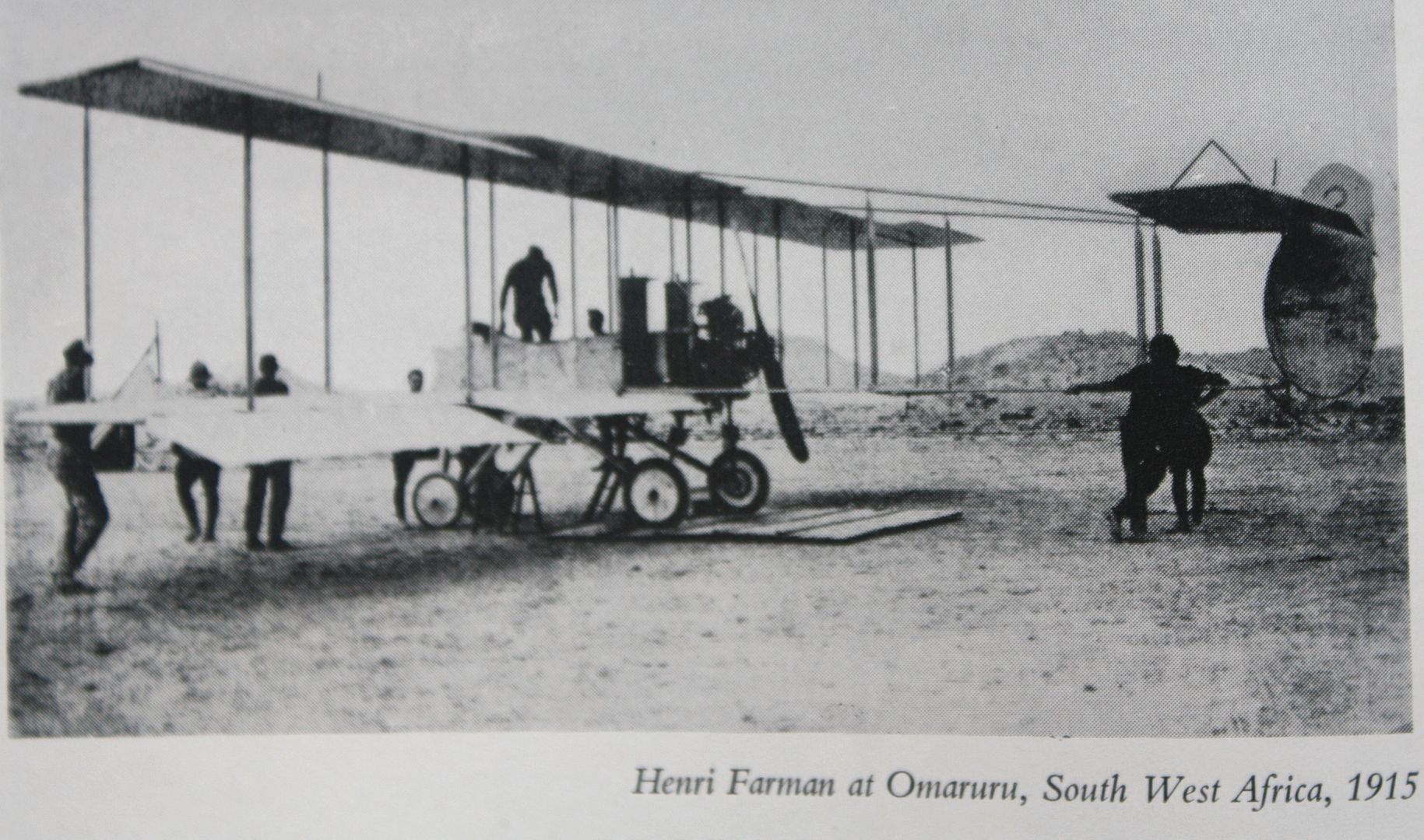
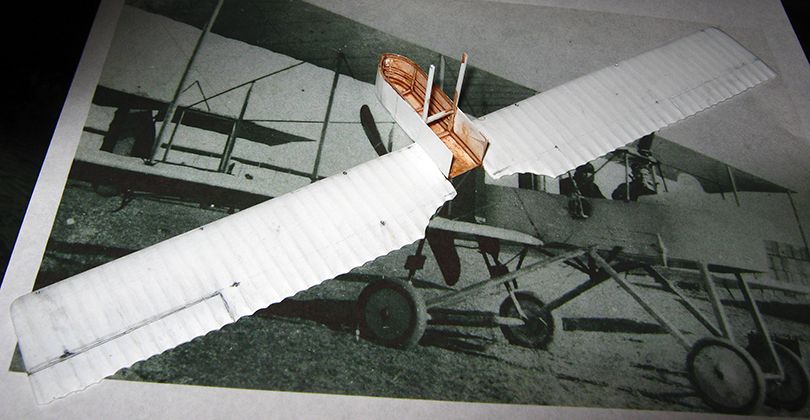
I only recently got a look at photographs which nailed down building this as a machine used by the South African forces in German Southwest Africa in 1915. Here is one of them:
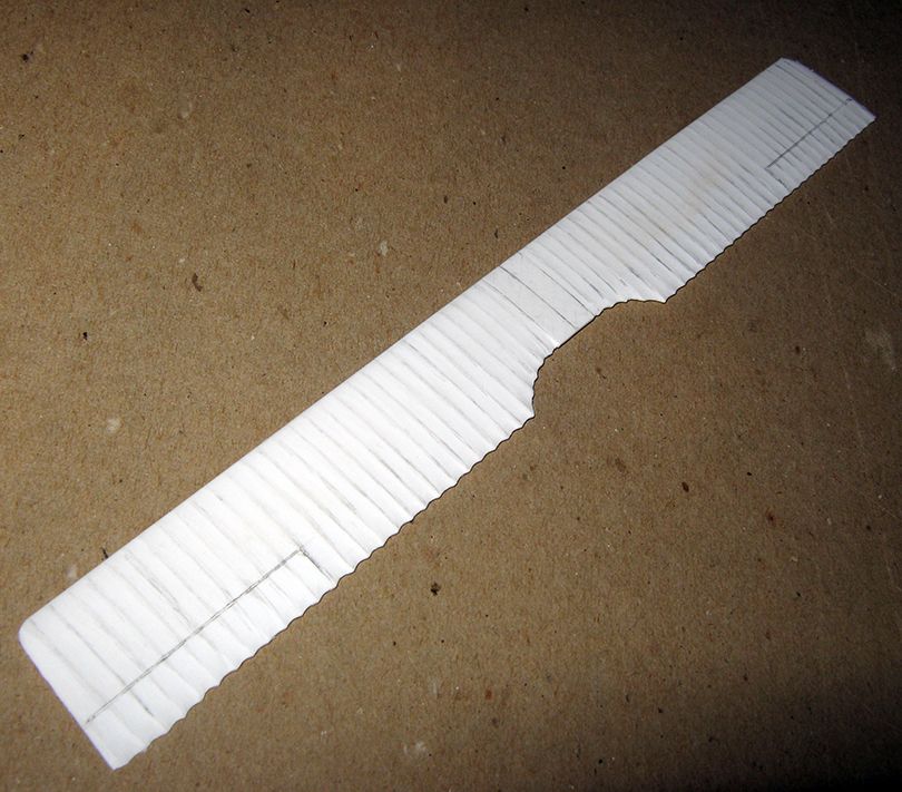
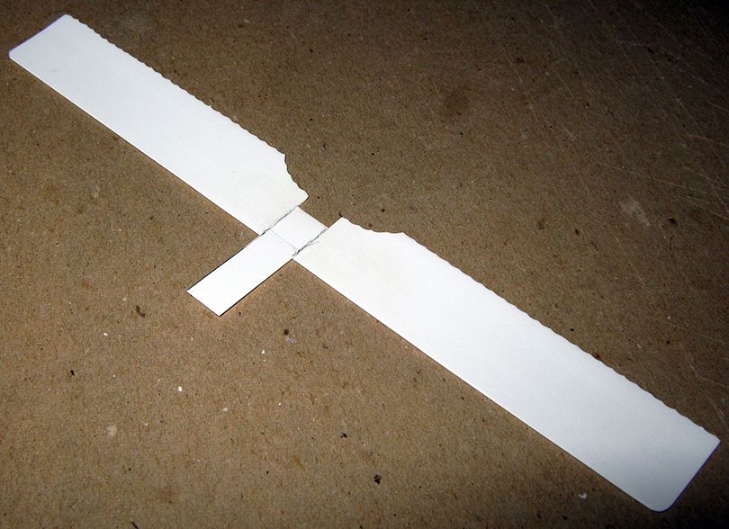
The project was started a few weeks ago, but I will begin at the beginning, which is usually the wings, as they are relatively easy, though laborious. The wings were made from 1mm sheet, and cold bent to camber, with the undersurface regularized by sanding with heavy paper taped to a large pill bottle, and upper surface sanded to necessary taper to front and rear. This took very little time, about an hour for both wings (as opposed to about eight hours, and a lot more dust, when sanding an airfoil section into thick sheet). Blank center on lower wing is where nacelle will go.
Here are the upper and lower wings with ribs established.
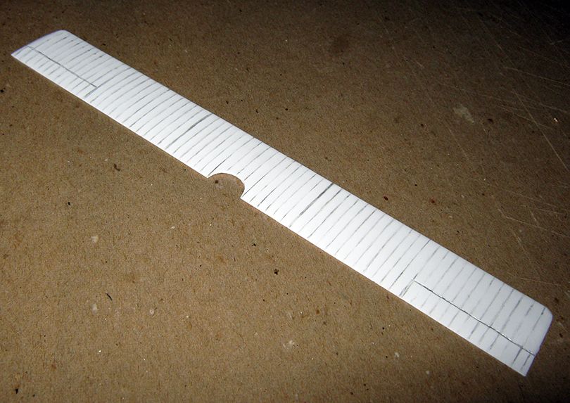
The pictures I can find of this machine show no traces of either cane strips or tapes reinforcing fabric at the ribs, so I have reverted to an old method of sanding and scraping the 'valleys' into the surface of the plastic, leaving raised 'ridges' between. A newer tool, however, Thin 'swizzle-stick' strips of sanding stick (replacing coils of sand-paper or sand-paper wrapped on various dowels) have been a great help in this. These 'swizzle sticks'are narrow strips of the padded emery sold as 'salon boards' in beauty sections (or as 'sanding sticks' by hobby suppliers). The strips run between 2.5mm and 3.5mm, which is a pretty good match with most 1/72 rib spacings, and come in grits ranging from very coarse to fairly fine. The ribs are marked in with pencil (best to work from the center out, rather then from one tip across to the other). Then the space between the linesis hit with one of these emery strips of coarse grit, taking care to leave the pencil marks intact. This is followed by scraping with the edge of a curved blade (a #10), which smooths things down a bit. Follow this with a narrower coarse grit emery strip, and then scrape again with the blade. It is one of those things which is simple to do by itself, but must be done right many, many times. With a little practice you can get fairly precise in the effect. Once every channel is in, I smooth further with something like 600 grit paper, moving chord-wise, not span-wise. After this a coat of primer (I use Tamiya Fine White, but everyone has a favorite), will give you a good surface.
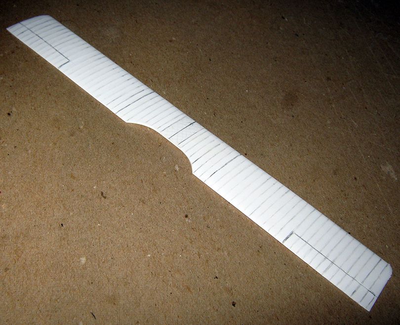
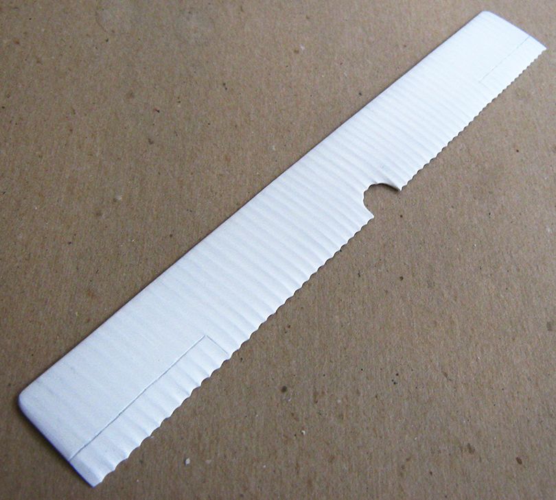
Here are the upper and lower wings with scallop trailing edges put in....
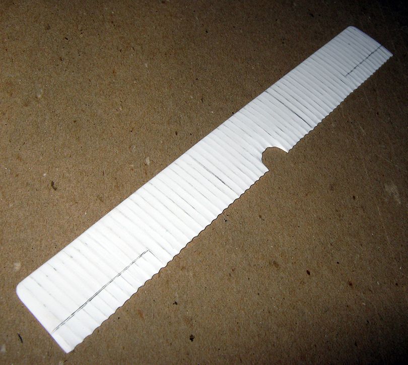
Scallops are cut in with a knife and regularized with a dowel wrapped in sand-paper. Rear portion of the wing surface is sanded and scraped down to get the trailing edge to a proper thin-ness. Some work was needed on the 'valleys' in the upper surface, but most of the thinning can be done to the under-surface.
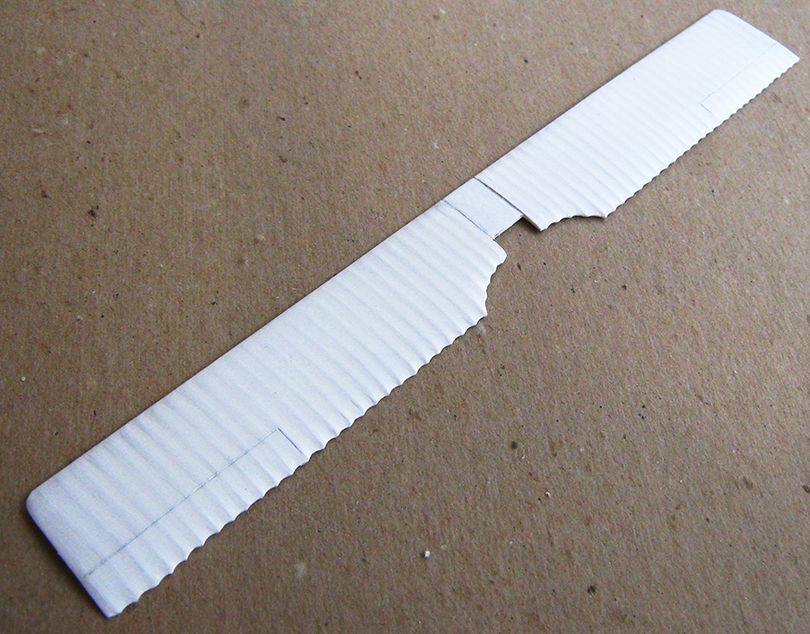
Here are the wings with a coat of primer....
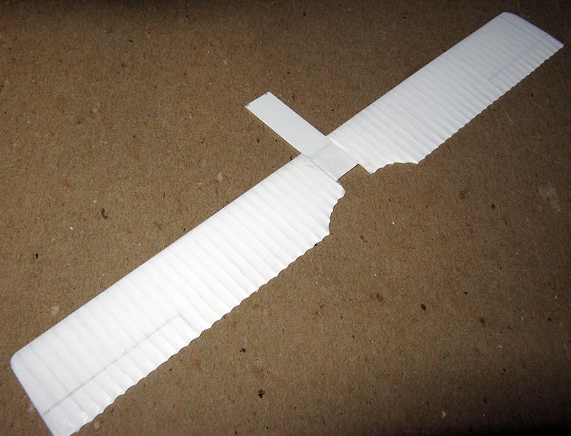
Since the nacelle structure is so interwoven with the struts and motor attachment, I decided the nacelle would have to be built with the lower wing (in the manner employed by the old Revell and more recent Eduard kits of the Dh-2).
Here is a piece of 0.5mm sheet cut to the proper length and width of the nacelle, shown first upper surface, then lower surface. It is not stuck directly onto the front of the wing piece, but rather the center was notched to receive it. After seams were eliminated, a sheet of 0.25mm sheet was added as binding reinforcement.
Here is the nacelle floor shaped, and with the parallel portion of the nacelle sides attached....
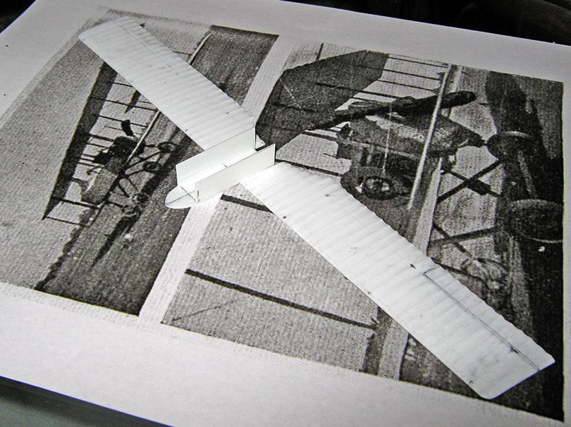
To be sure things were the same height, I cut a long strip of 0.25mm/10thou sheet, and trimmed out of it two lengths running from the rear of the covered portion to where the bend begins to provide the sides.
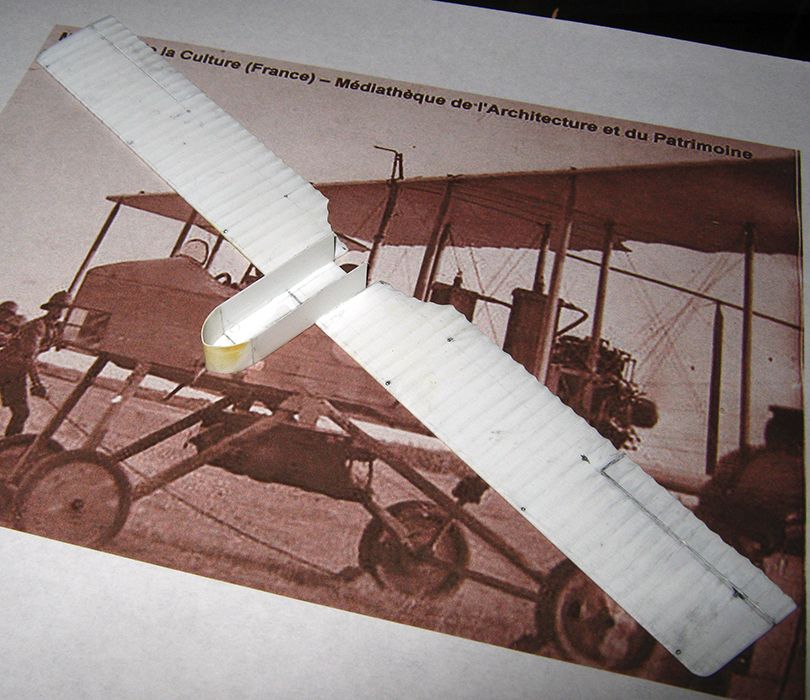
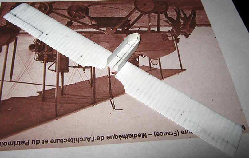
For the nose, I took a length of the remaining strip sharp bend got the 'point' and pressing with a tweezers got the rest of the rough shape. Lying this over the piece got me some pencil lines for cutting, and once it seemed to fit glue was applied, to the bottom and the mating edges. Wife lent a third hand here, as both mine were fully occupied holding the wing the new bit in place at the proper curves, and she dropped a good deal of accelerator onto the general area. Things held well, and then it was just a matter of a bit of patching in a small gap on the port side and general seam cleaning, inside and out....
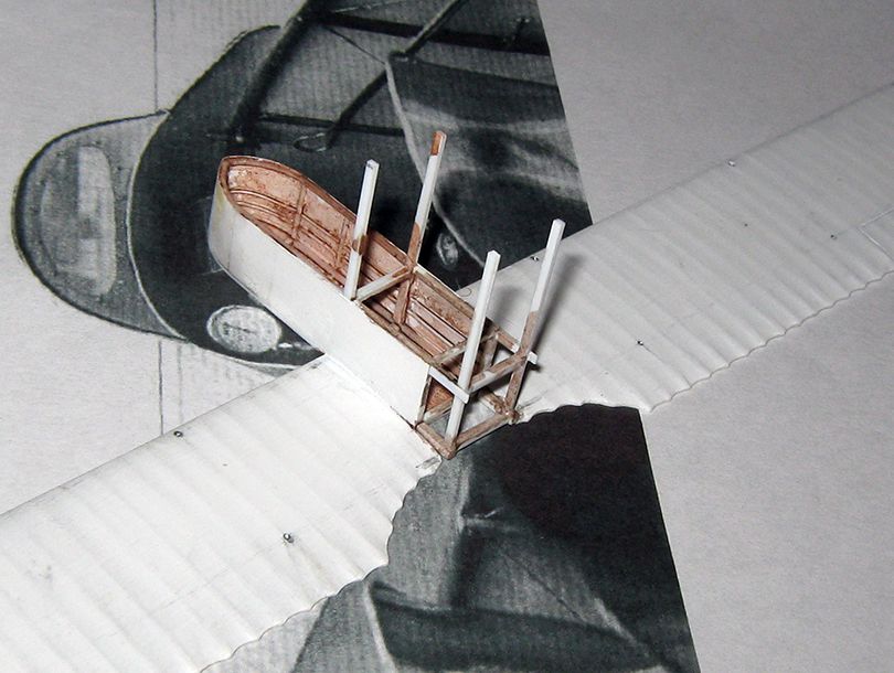
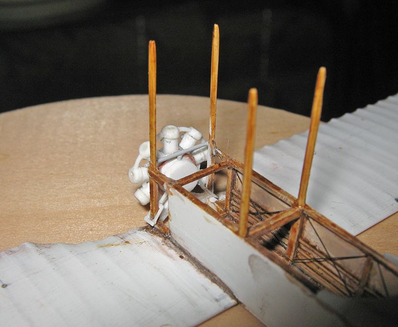
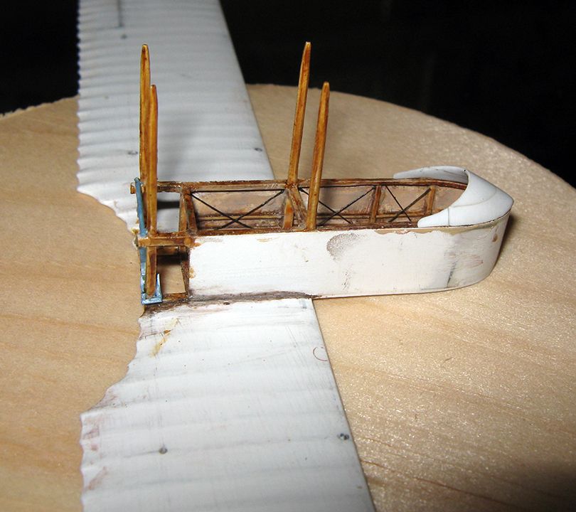
I started the internal structure with 0.5mm rod laid around the joint of floor to wall. I then started on the verticals. My intention was to do just the portion of the forward central interplanes that were under the rim of the nacelle, but I used a longish bit of 1mmx0.5mm rod to do so, figuring this would be easier to align and that I could trim it down later. But it seemed so well aligned with the locating holes for the rest of the struts that I figures to go with the flow, and trimmed it of at the proper strut length (27mm from the lower wing surface). I put in its mate on the other side, and built both up with an additional length of 1mmx0.25mm strip, and proceeded to do the rest of the structure of the crew area of the nacelle....
I then did the structure in the rear portion of nacelle, including the rear central interplanes....
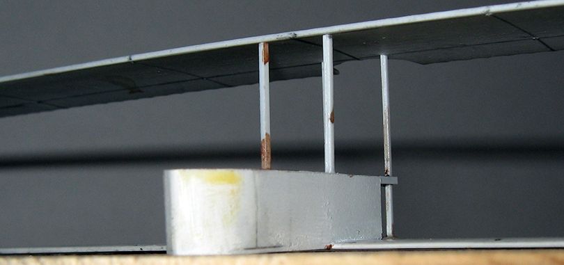
At this point, I gave the upper wing a shot at resting on the central interplane struts, and I was, and remain, reasonably happy with their spacing and alignment....
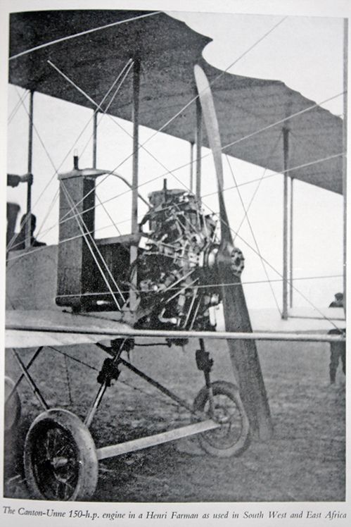
There were several false starts on making and mounting the motor, but then I got this picture of a South African machine, which wife cleaned up a bit in Photoshop, pulling even more detail out of the shadows....
Some reworking of the extreme rear of the nacelle was required, but nothing too serious.
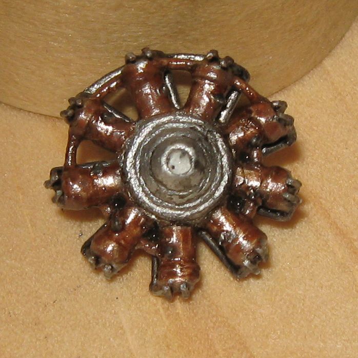
Here is the motor in early stages, fitted to its bearer and mountings, on a partially re-worked nacelle rear:
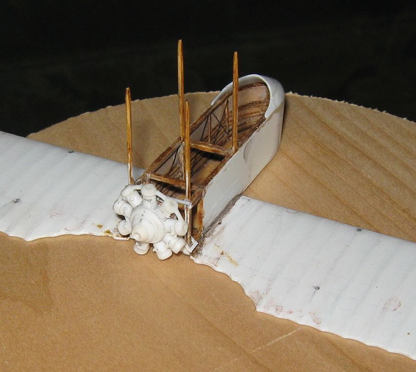
The motor started with a central disc out of 2mm sheet, which once I had locators holed for the cylinders (using a spare 9-cylinder radial as a template) I sanded to nonagonol faceted. The cylinders are lengths of 2mm rod, with caps of 2.5mm rod added later. Discs of 1mm sheet, one in front and two in back, wre added to the crank-case, and the basic blank was in hand.
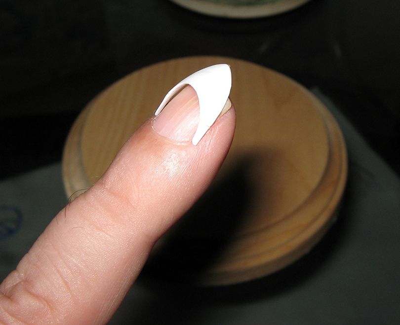
The interior has been painted, and most of the internal rigging put in (with painted 0.004" brass wire). The nose 'cap' is just resting in place. This was made from a block of two rectangles of 2mm sheet laminated together, after which everything no the desired part was cut and sanded away. A bit of extension was added in the rear on each side, but these may be cut off, as they do not seem to be evident in the S.A. pictures. Wife has previously remarked on seeing items like this that they resemble the 'stick on' nails girls use nowadays, buyable by the pack in the beauty section, and she may have a good point....
Here is a look at the nacelle rear in final form, ready for the motor to be attached....
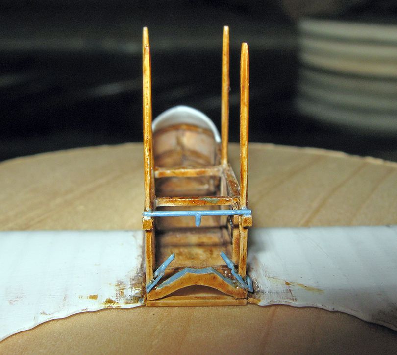
(I notice in these pictures I knocked a bit off the port 'shackle': it has been replaced)
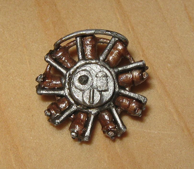
Here is the engine, painted, about mid-way through detailing, front and back...
Here is the motor with lifters and rods and ignition leads complete:
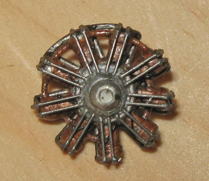
Copper tone is a wash of brown over sprayed silver, topped with clear orange (washable marker picked up with Future).
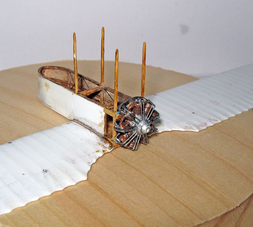
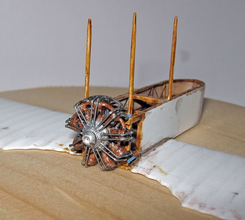
Finally, here is the motor attached to its mountings at the rear of the nacelle.
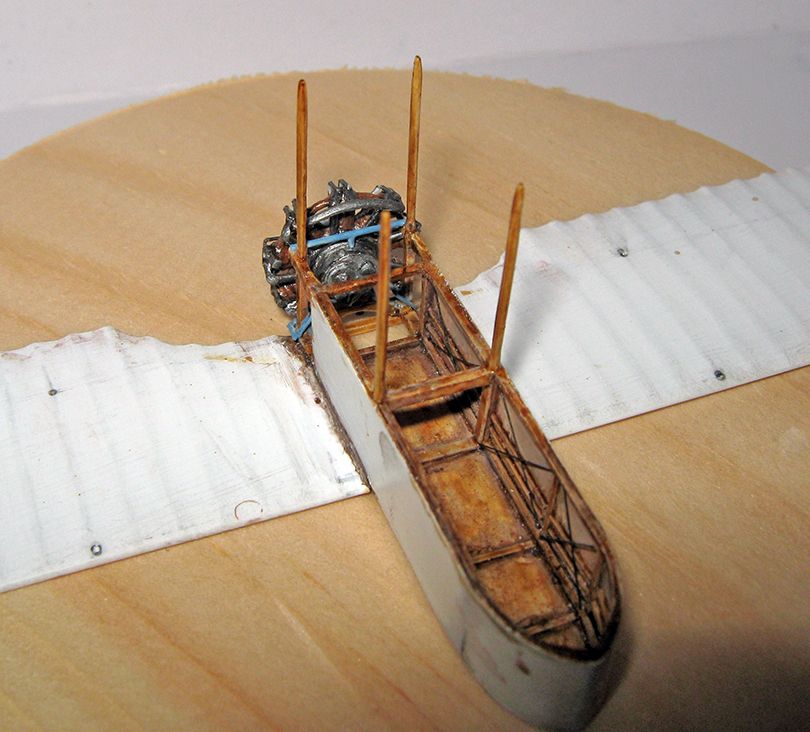
I have now begun doing the interior furnishings (seating arrangements and fuel tank are already in hand), and once that is complete, will be able to finish the exhausts and do fuel feeds, paint the large pieces, and then do the radiator and water-pipes. I am hoping to get through that lot this weekend....