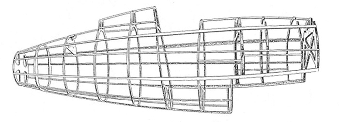
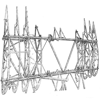
The short fuselage was made forthemost in pine wood, ash and plywood with steel bracing reinforcements.
There were 11 frames, 4 longerons and 8 stringers.
Image from Scalemodels.ru
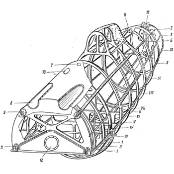
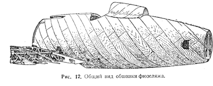
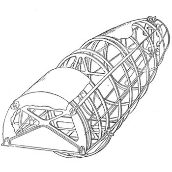
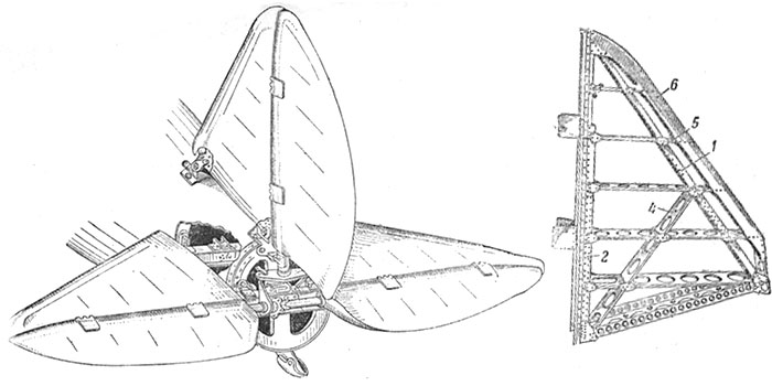
3/4 view of the wooden structure of the fuselage, with the frames numbered.
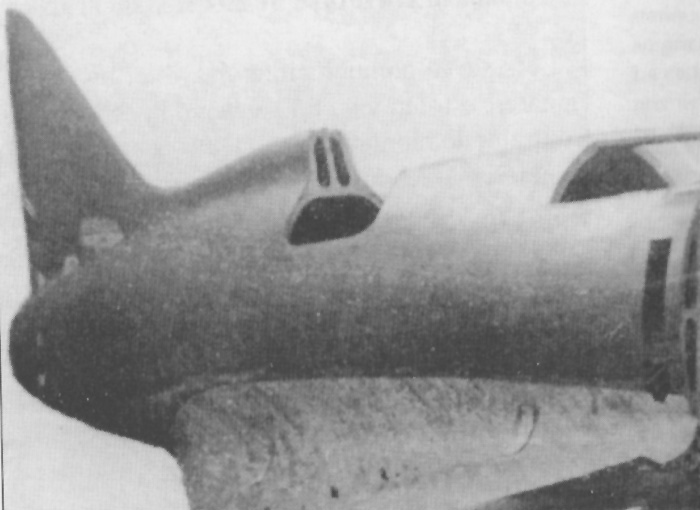
The recesses on the nose were for the synchronized ShKAS.
Image from Scalemodels.ru
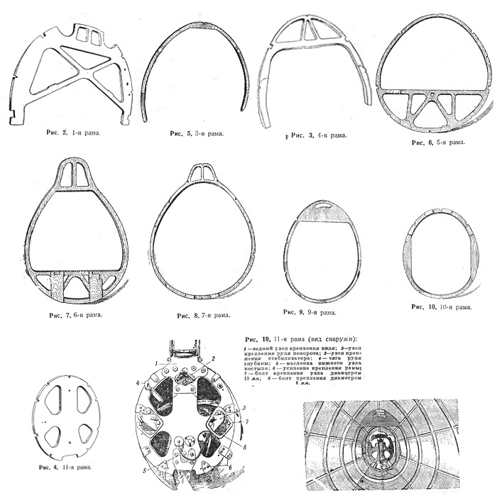
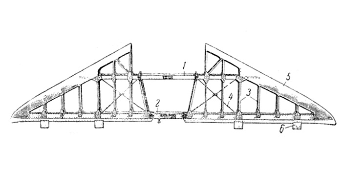
Drawings of some of the frames of the fuselage, make reference to the drawing above to locate them.
- 1st frame
- 3rd frame
- 4th frame
- 5th frame
- 6th frame
- 7th frame
- 9th frame
- 10th frame
- 11th frame
- Fig.19: 11th frame and the fuselage from behind, with the tail cone removed
- Last: Image of inside the rear fuselage.
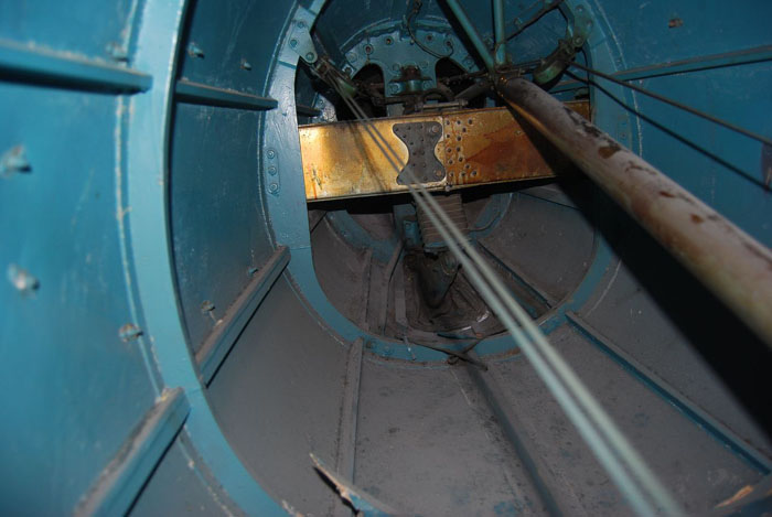
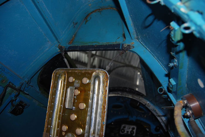
Photo of inside of the rear fuselage of the Type 5 preserved in Chkalov Museum.
The large articulated rod is moved by the cloche and is for the elevators.
The cables on the sides are from the pedals, and control the steering both of the rudder and of the tail skid.
The transversal metallic beam is the longeron of the stabilizers.
At the end, we see the final frame, oval with 4 openings. Beyond that there was the metallic tail cone.
The turquoise color of the inside is a surprise. It's not clear if it was made in factory (grey A-14 would be expected) or during the restoration of the plane.
From Scalemodels.ru
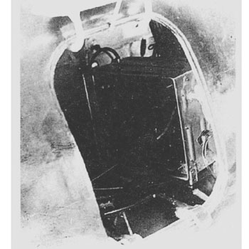
Another photo of the Type 65 in Chkalov museum: this shows the unarmored backrest of the seat and the cockpit.
The plug on the right side could be connected with an insulator for a radio wire; another insulator (not visible in this photo) was on the back, behind the headrest, slightly moved on the left.
From Scalemodels.ru
The shell covering was made of shpon, made of stripes of birchwood bonded together with casein glue, with each layer perpendicular to the lower one to gain strength.
The shell was in two halves, divided on the vertical plane and fitted around the carcass by zinc pins and casein glue.
Plywood was used to reinforce junctions, cut-out sections and mountings.
The shpon of the top half was 5.5 mm thick, the lower front half 2.5 mm, and 2 mm on the rear section.
From Scalemodels.ru
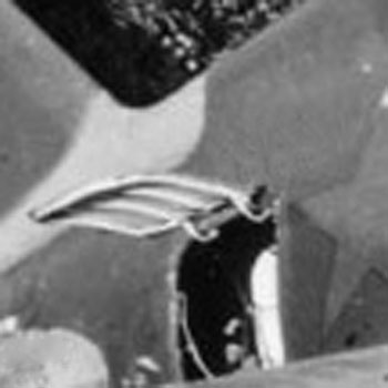
On late production I-16 (Type 24, 28, 29) a panel on the right side, located between frames 7 and 8, gave access to the radio and other equipments.
When closed, the panel was a bit raised on the skinning of the fuselage.
From the web
After the fitting of the centreplane and its fillets, all the holes and irregularities were filled with a nitro putty. then the surfaces were coated with nitrocellulose glue on which calico was affixed.
The fuselage received a final layer of yellowish putty before the final painting.
The inner surfaces of the fuselage were painted in factory with grey enamel A-14 up to 1940, then it was replaced by light grey nitro AKh-9 for planes built in 1940-41.
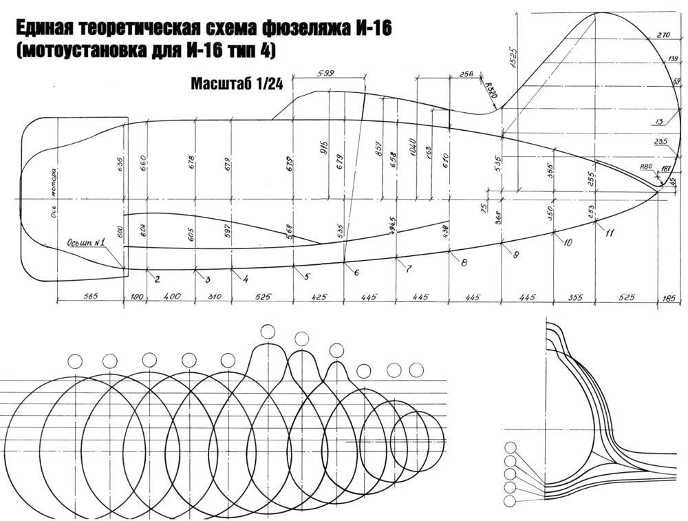
Below: a factory drawing with measures of the struts of I-16 Type 4. The fuselage hasn't changed by much in successive versions.
From Scalemodels.ru
 From
Scalemodels.ru
From
Scalemodels.ru
Measures of UTI-4 from its manual.
From Scalemodels.ru
The struts of the fuselage of UTI-4.
From Scalemodels.ru
The centreplane consisted in two stainless steel spars connected with duraluminum ribs and tubular struts.
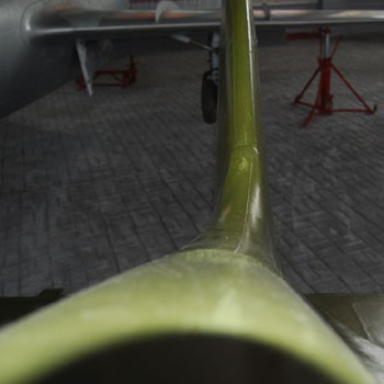
The joint between the wing and the fuselage was forthemost covered by wood but some duraluminum was used in its rear part.
Over the wings, there were metallic hatches giving access to the wing weapons (on all versions except Type 29 and UTI 2/4).
On the drawing aside, the presence of six locks for each panel is characteristic of ShVAK-armed versions (type 12, 17, 27, 28). ShKAS-armed versions (Type 5, 10, 18, 24) had panels with the same width but a bit shorter and with four locks each.
From Scalemodels.ru
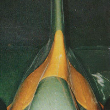
Left: the centreplan-wing console joint visible after the remotion of the metallic stripe covering it.
One can also see the open bay for a ShVAK gun, recognizable for six locks instead of four as for the ShKAS.
From Scalemodels.ru
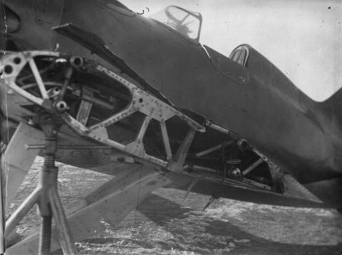
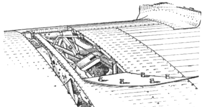
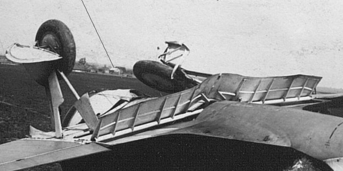
Image of a damaged plane Type 10 without the outer consoles. The strut of the centreplane is visible.
One can see even a ShKAS machine gun inside; the curved tube for waste links expulsion is visible: it ends in an hole through the metal skinning under the wing.
The lower surface under the centreplane was made not in wood, but by removable metallic panels.
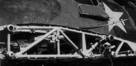
Below: similar detail form another plane. Here the strut looks a bit different, made with welded tubes instead of duraluminum profiles.
From Scalemodels.ru

Above: interesting image from a burned wreck, showing many details of the centreplane, of the landing gear of a Type 24 and the shape of its bays, of the feeding of its wing ShKAS (that seem missing).
Details of the exhaust pipes of the engine are interesting too. The cylindrical black thing at the center was the oil cooler. Note that the main wheels bays were in a removable panel, missing on the image.
Image from Scalemodels.ru.
Pneumatically-actioned flaps were introduced first in Type 10 at the beginning of 1938.
This was a way to contrast the increased take-off and landing run due to the additional weight of the synchronized ShKAS.
Here we see the flaps in open position, their frame and the wing/fuselage surfaces closing their bays.
Image from Scalemodels.ru
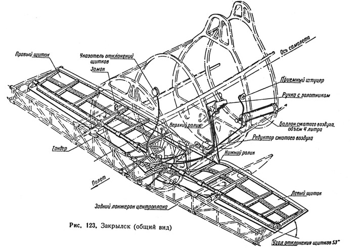
A scheme showing the pneumatic actioning of flaps in a Type 10/17.
The opening suddenly braked the plane in flight, and wasn't safe.
In 1939, this system was replaced by a mechanic one that allowed a more gradual movement.
From Scalemodels.ru

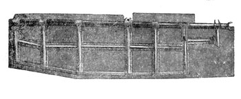
Some images of the flaps. Note the tubular shaft. Three hinges are mounted in front of the shaft.
From Scalemodels.ru
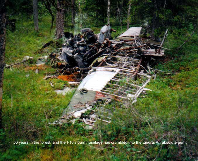
Image of a wrecked I-16 recovered.
Many metallic parts are still well recognizable, but the wooden parts were lost.
The metallic structure of the wing console is well recognizable. A part of the fabric skinning, still with somewhat preserved original colors, shows that the fabric covered the metal-skinned parts too
Image from Scalemodels.ru
Each outer panel of the wings had two longerons mainly made with two steels tube each, joined by smaller struts.
Each console had 11 full duraluminum ribs, plus 11 half-ribs to strengthen the part of the upper surface that had fabric skinning; these were introduced in spring 1937 because the earlier type of wings, without the half-ribs, was more prone to damage.
A wide part of the upper surface, the leading edge and a smaller part of the lower surface had duraluminum skinning.
A layer of fabric covered both the areas left uncovered by the metal sheet, both the covered one, and was glued on it.
To become more rigid, the fabric was painted with two layers of clear lacquer, followed by two layers of green on the upper surfaces and three of light paint (aluminum or light blue) on the lower surfaces.
The gaps between the centreplane and the outer consoles were covered by duraluminum strips; one fastener (up to Type 10) and two fasteners (later types) were used to keep the strips in tension.
The ailerons were made with a duraluminum structure, covered by fabric. Trim tabs were introduced only on late type 10/17, and sometimes refitted to older planes. They were simple duraluminum plates that could be bended by live force to improve the balance of the aileron.
The illustration shows the typical ailerons of Type 5, UTI-2 and 4, that were longer than the wing consoles because they weren't equipped with flaps under the centreplane.
Starting with Type 10, all successive fighter versions had flaps under the center plane and shortened ailerons, not extending inside from the consoles joints.
Type 4s and TSKB-12 had slightly different ailerons: long as those of Type 5, but with hinges moved under the wing undersurface and more gap with the wings.
From Scalemodels.ru
The wing of a late type I-16, perhaps Type 24P (with auxiliary tanks).
They were distinguishable on the uppersurface for a hatch giving access to the auxiliary tank suspension point (well visible on the photo) and, on the lower surface, for the metallic plate with the suspension point for droppable tanks (on both wings) and for landing flares (under the right wing only).
On rockets-armed versions (Type 28R and 29) there were also metal-skinned areas for the rocket rails ( on both wings), protecting the lower surface, the ailerons and the leading edge up to a part of the upper surface against the fire of the rockets.
Type 5 and 10 converted into ground attack planes with rockets had metal plates under the wings, but they could not be extended to the leading edge and upper surface.
From Scalemodels.ru
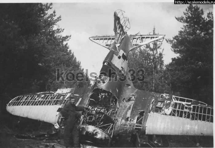
Image of a wreck of a Type 24. The fabric layer has ben stripped down by souvenir hunters, showing the internal metallic structure.
The fuselage was broken and the fuel tank looks missing;some light is visible on the back of the instrument panel.
A black bottle for filler is visible close to the instruments.
The stripped down areas on the fuselage should show the yellowish color of the putty filling the wood skinning under the removed fabric layer.
Image from Scalemodels.ru
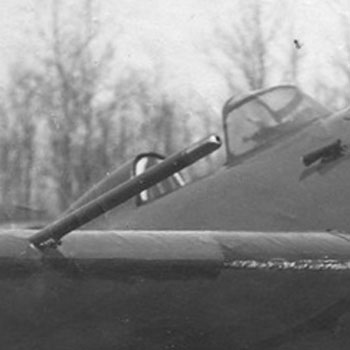
Left:
The photo shows the pitot probe; note that it was installed above the leading edge. It was common to all types.
Right:
the non-retractable landing flares under the right wing of a Type 4. Probably the same possibility of installation was maintained on all versions, except for those that had extractable flares (Type 24 R, Type 29, late UTI-4)
Image from Scalemodels.ru
Left:
one of two extractable landing flares on the right wing of the UTI-4 preserved in Finland.
Right:
detail of the wing of a Type 24R or 29 showing the extractable landing flares on a metallic plate, the mounting points for 3 rocket rails over a metal-reinforced skinning, and the plate with bomb racks installed in place of the auxiliary tank suspension plate.
Images from the web
Right: detail of the installation of RO-82 rails under the wings of a Type 5 converted to ground attack plane during the war.
A metallic plate was put on the skinning under the wings in the rocket area of each wing; lines of rivets are recognizable on the photo.
It is unclear if the protection was extended to the leading edge of the wings of these old types, as it was on Type 28R and 29.
Image form Sa-Kuva archive.
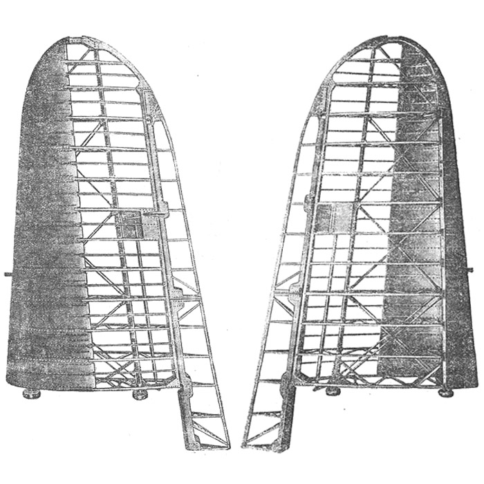
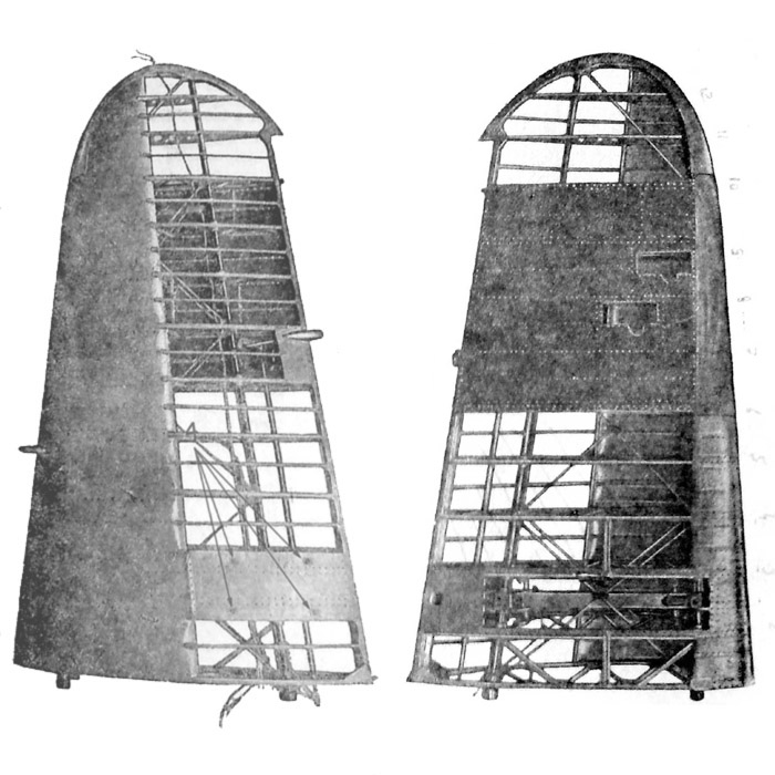
The tail empennages of the I-16 had a duraluminum structure covered by fabric.
Small elastic plates fixed to the fin and stabilizators covered the recesses of the hinges on the rudder and elevators to improve the airflow.
From Scalemodels.ru
Drawing of the duraluminum structure of the stabilizators of I-16
From Scalemodels.ru
A prominent characteristic of the fin was its asymmetrical collocation: on all M-25-62-63 engined types it was inclined of 2° to the left to compensate the torque of the propeller, that rotated counterclockwise.
On M-22 engined types, as TSKB-12, Type 4 and UTI-2, the propeller turned clockwise, and the fin was inclined of 2° to the right.
Left:
image of the fin of the UTI-4 in the Finnish museum.
Right:
image of the fin of the Type 5 in Chkalov museum.
(images from Scalemodels.ru)
Left:
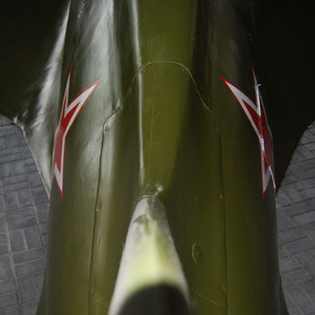
again the fin of the Type 5 in Chkalov Museum, from its tip.
Right:
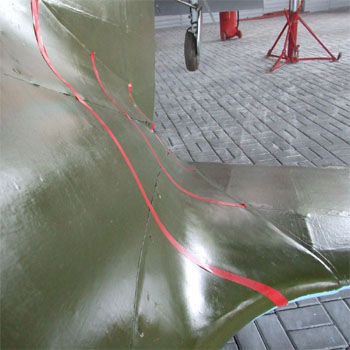
this image of the Type 5 of the Chkalov museum has some red adhesive tapes that put into evidence the shape of the section of the metallic fillets of the fin and of the stabilizers.
(from Scalemodels.ru)
Left:
the tail fillet of a Type 18 (the code 1821..... is readable): its outer profile is without interruptions.
Right:
the tail fillet of late UTI-4 preserved in the Finnish Air Force Museum shows an interruption in the profile and a small oval hatch closed by two screw to give access to something inside.
This modification appears on Type 24, 28, 29 and late UTI-4, perhaps related to some internal improvement appeared with the tail wheel.
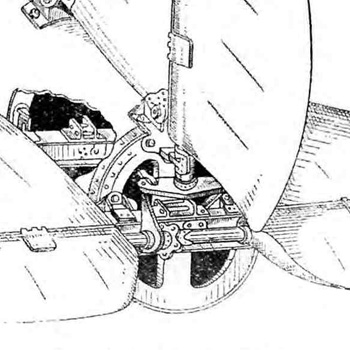
Left:
drawing of the tail with the tail cone removed. We can see the shaft for the elevators and its lever, and the shaft of the rudder and relative levers.
Image from Scalemodels.ru
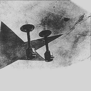
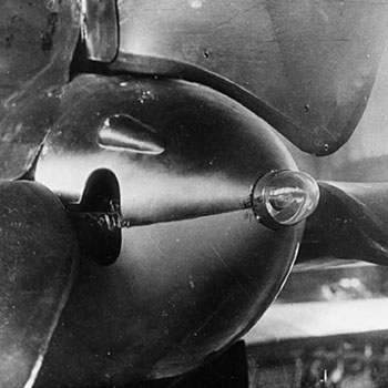
Mid left:
tail cone of I-16 Type 4. The tail cone is made of two parts, the forward part with the hole for the rudder shaft, and the rear one with the side holes for the shaft of the elevators and the final white/amber position light.
A characteristic of Type 4's cone (and probably of UTI-2's too) was the small blister on the left side to give space to the lever of the elevators shaft.
Image from Istrebitel I-16 of Maslov
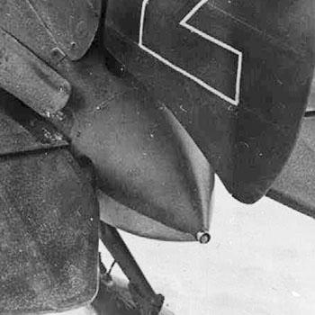
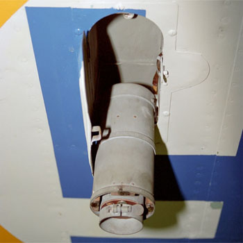
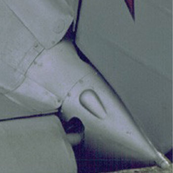
Left:
the image of the tail cone of a Type 5 shows that the blister has disappeared, and the openings for the shaft of the elevators has become smaller. It is not clear if the lever of the shaft has become smaller than on Type 4 or what else. Note that the fillet of the stabilizer appears a bit out of its place.
Right:
detail of the Type 5 preserved in the Chkalov museum. Again, no blister.
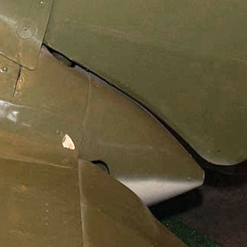
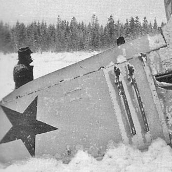
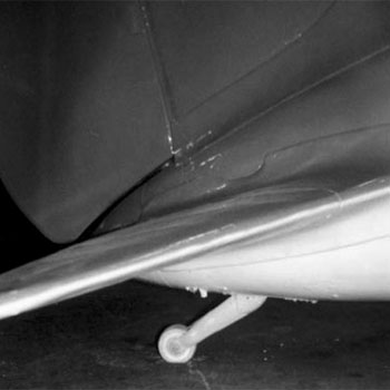
Left:
the tail cone of the UTI-4 of the Finnish Air Force museum. Again, no blister. Here the position light is missing.
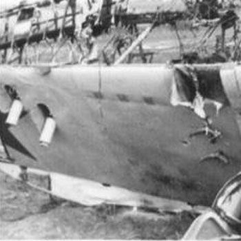
Right:
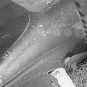
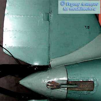
the tail cone of the Type 28 preserved in S. Petersburg Navy Museum from below.
The metal stripes screwed on the rear fuselage are noteworthy, as the tail skid (unusual for a Type 28, it comes surely from an earlier plane).
The small metal U protruding under the stabilizer is not original, but a museal adaptation for suspending the plane to cables.
Image of Arsenyev from moskittech.ru
Left:
the tail cone of a recent flying replica. Surprise, it has the blister and the large shaft openings just as that of Type 4.
Although being undoubtably I-16s, the flying replicas haven't an exact match into any I-16 type.