PV-1
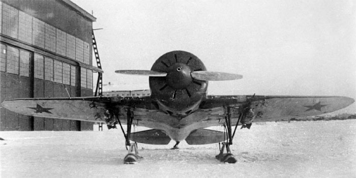
The TsKB-12 was projected to be armed with two ShKAS firing outside the disk of the propeller but, in their initial configuration, they were prone to jamming, also because one of them was mounted upside down because of the feeding from their left side only;
Waiting to resolve this problem, they were replaced with two PV-1 machine guns.
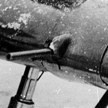
Probably the replacement was limited to few planes, because it's difficult to find photos of TsKB-12 or Type 4 with this armament, whose barrel and manifold were well distinguishable from those of ShKAS.
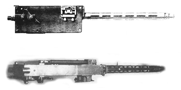
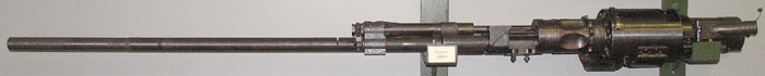
The Nadashkevich PV-1 was an adaptation of the famous Maxim 7.62 mm for aviation use, started in 1923. The main modification was the change from water-cooled to air-cooled to save weight. The weapon passed the state tests at the end of 1926; in spring 1927 it was compared favourably to the Vickers, and in 1928 it was adopted for the fighter I-2. In 1930, it was started the production of a variant feded from the right instead of from the left for the fighter I-4. Later, the PV-1 was installed on I-5 and I-15 and on some TsKB-12.
18000 PV-1 were produced between 1927 and 1939, then it was discontinued in favour of the ShKAS.
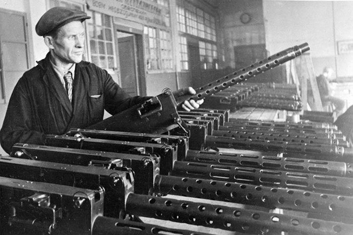
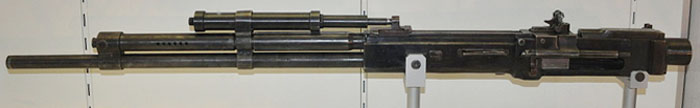
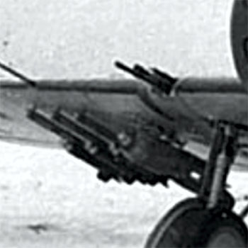
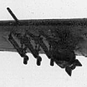
This photo of a factory or maintenance device shows that the manifolds of the PV-1 could had both long venting slots or circular venting holes on their manifolds. The barrel of the version with holes has resemblance to that of the Browning machine guns.
Image courtesy: Andrey Averin
Caliber mm: 7.62
guns Length, mm 1067
Barrel Length, mm: 721 (early 673)
Mass kg 14.5
automatic type: short recoil barrel
Firing rate: 800-865 rounds to minute
Early. projectile speed, m / s: 750
Type of cartridge: 7.62 x 54R
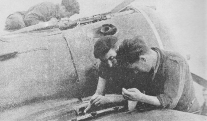
The Spanish Republican Air Force received a batch of early Type 10, still with the M-25A engine; this was the first version to have synchronizrd ShKAS on the nose, in addition to those on the wings.
The first combat revealed that there were problems in the synchronization of the ShKAS on the nose; they were replaced by older PV-1 taken from I-15s, that had a lower rate of fire.
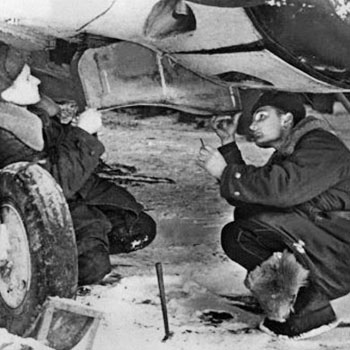
The photo aside shows Spanish technicians working on an I-16 type 10. The squared shape of PV-1 machine guns can be recognized.
Image from a book on the FARE of Patrick Laureau, Docavia 1978.
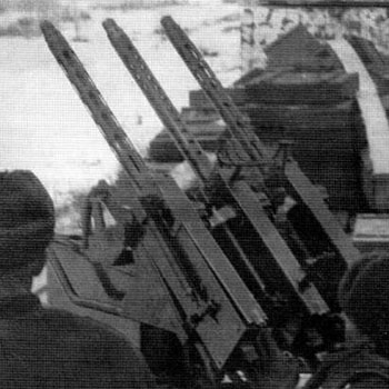
During the war, recovered PV-1s were adapted as infantry and AA weapons.
ShKAS
The problem of the feeding was soon resolved, and the ShKAS took their place in the wings of I-16 replacing the obsolete PV-1.
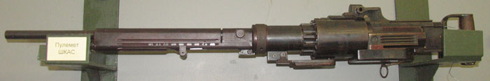
The ShKAS (Shpitalny-Komaritski Aviatsionny Skorostrelny, Shpitalny-Komaritski rapid fire for aircraft) was designed by Boris Shpitalniy and Irinarkh Komaritsky and entered production in 1934.
When it appeared, it was an innovative weapon, characterized by an high rate of fire (1600 rounds/min) and light weight; so it became the standard weapon of Soviet fighters and bombers in the second half of the '30s up to 1942.
It was not very reliable due to its high rate of fire, besides an unwise use of it led to a quick end of the shells cases.
Despite its interesting praises, at the war outbreak the ShKAS was already obsolete because the planes had became more resistant to damage, and weapons of larger caliber were needed for an adequate lethality.
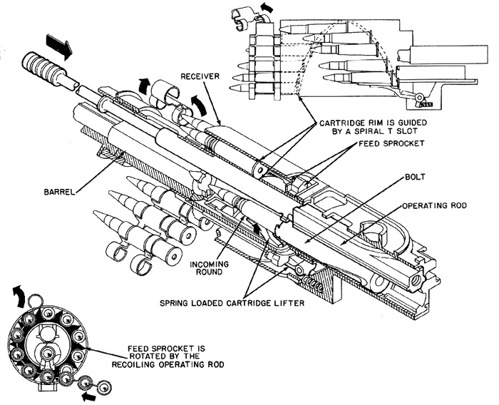
ShKAS was a gas-operated revolver-type machine gun; it had a single chamber in which the pin striked the primer.
Two keys characteristics for the high rate of fire were:
- the revolving drum (feed cage) holds ten rounds and provides a very smooth, progressive removal of the cartridges from their disintegrating link belt;
- the recoiling portion of the gun with a mass of only 921 grams, and low inertia.
https://en.wikipedia.org/wiki/ShKAS_machine_gun
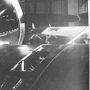
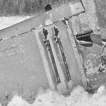
Left:
a ShKAS in the wings of a TsKB-12/I-16 Type 4, mounted in the right way.
Right:
detail of the barrel of the ShKAS on the left wing. The blister seems shorter than the one of the successive types.
Images from Istrebitel I-16 of Maslov
Left:
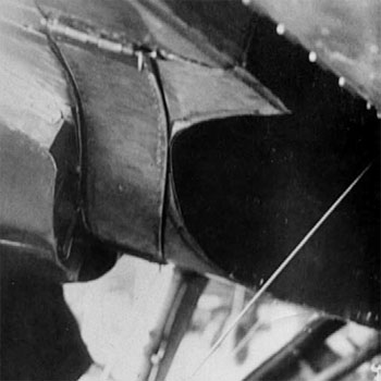
The ammo box for the wing ShKAS (or PV-1) was located under the fuselage between the landing gear bay and the cowling.
Between the cowling and the bay of a TsKB-12/Type 4, we can see one of the hatches for the ammo boxes of two 7.62 mm machine guns in the wings.
Images from Istrebitel I-16 of Maslov
Right:
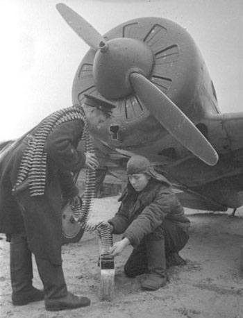
the ammo loading of the ammo boxes of a I-16 Type 5 M-25V, surely armed with ShKAS on its wings.
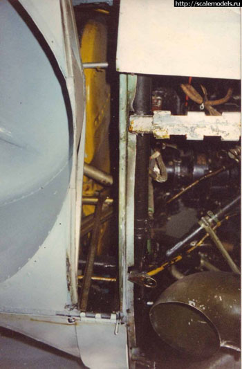
Left:
the ammo box for wings installed ShKAS on a I-16 Type 5 or 10, opened on field conditions.
Right:
the vane left open on the Type 5 in Chkalow museum. The yellow thing is the fuel tank.
This hatch was preserved, with different use, in all I-16 versions except for Type 29 and UTI-2/4.
The armament of Type 5 of two ShKAS only was deemed unsufficient due to the experiences of the Spanish Civil War.
In early 1938, the I-16 Type 10 was introduced into production; its main progress was the introduction of two synchronized ShKAS on the nose, in addition to those on the wings. The nose-mounted ShKAS were preserved in all successive fighter versions of I-16.
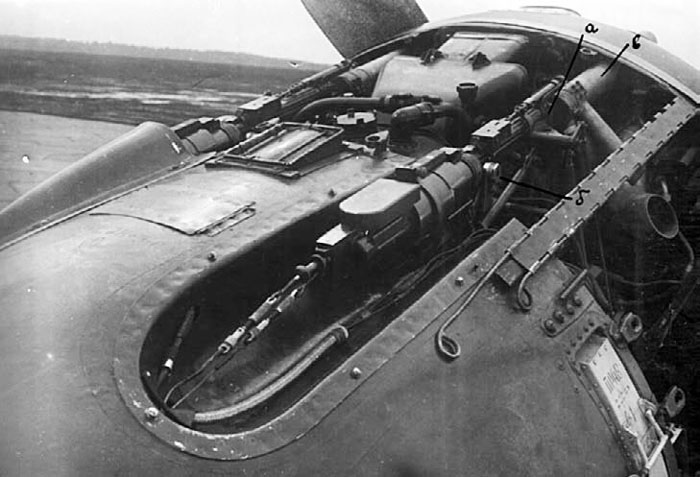
The photo shows the open cowling of a I-16 Type 29.
The synchronized ShKAS are well visible; the barrels entered into the blast tubes, that ended outside the engine cowling.
On the side, the ammo box for the right ShKAS is well visible. When the cowling was mounted on, the ammo boxes were hidden.
On Type 4, 5 and early Type 10 the side plates of the engine were made in one piece, so they had to be removed to give access to the ammo boxes. Starting from late Type 10 and 17, the cowling side was splitted, so the rear part of it was removable as a separate piece to give quicker access to the ammo boxes.
The synchronized ShKAS were enclosed in longitudinal blisters, that altered the profile of the plane.
All what we see here relative to the armament should be common to all M-62 and M-63 engined versions, except for the raised central hatch for the ammo loading of the UBS (Type 29) or for the wing ShKAS (Type 27-28), absent on Type 18 and 24.
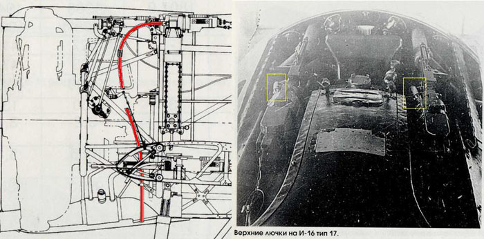
Image of the ShKAS installation on a Type 17. The image puts into evidence the pipes for the waste links expulsion, that reached a couple of holes on the lower part of the cowling.
The yellow contours on the photo show where the tubes start from the weapons.
The drawing puts into evidence the installation of both the nose ShKAS and of wing- mounted ones on I-16 Type 10.
Image from Scalemodels.ru
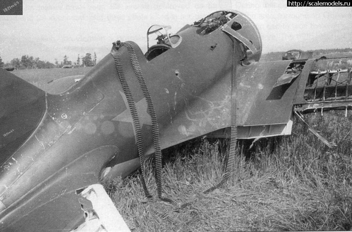
Image of a Type 18 captured and vandalized by Germans.
The ammo belt of the right synchronized ShKAS was extracted from its vane.
Note the separate panel (crudely distorted) on the sides of the cowling to give quicker access to the ammo boxes; the split of the side cowling panels was introduced in late Type 10 and 17 and preserved in all successive fighter versions.
On the wings, the access hatch of the wing-mounted ShKAS was crudely opened. The panel was locked by 4 locks.
Image from Scalemodels.ru
ShVAK
The ShVAK (Shpitalnyi-Vladimirov Aviatsionnyi Krupnokalibernyi, "Shpitalny-Vladimirov large-calibre for aircraft") was an enlarged derivative of the ShKAS.
It was designed by Boris Shpitalniy and Semyon Vladimirov and entered production in 1936. .A first version was made with a 12.7 mm caliber, but it was of difficult production and was abandoned after a limited production in 1935.
The 20 mm caliber became the standard for this weapon; its producton in this form started in 1936.
At least four version existed:
- MP for the tank version (total length 2122 mm; weight 44.5 kg)
- KP for the wing-mounted version ( total length1679 mm; weight 40 kg)
- TP for flexible mounts ( total length 1726 mm length; weight 42 kg)
- SP for synchronized installations.
ShVAK were installed in many models of Soviet aircraft; about 100000 ones were built between 1936 and 1946.
The first I-16 type to receive this armament in the wings was the Type 12, built in very limited number; the gun-armed Type 17, 27 and 28 were built in larger numbers.
https://www.forgottenweapons.com/light-machine-guns/shkas-aircraft-mg/
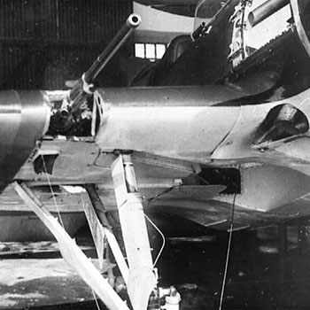
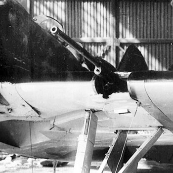
Two details of a Type 17. The ShVAK gun barrels are noteworthy, and common to Type 12, 27 and 28.
The waste shells expulsion slots are located differently from those of the wing ShKAS of other types.
The waste links were expelled forward through a short pipe on the right/front/lower part of each gun barrel, slightly protruding from the same opening on the leading edge.
The photos show the small waste link expulsion tubes of the synchronized ShKAS, protruding behind the exhaust pipes opening.
detail of the opening of the barrel, closed with a plate on a Finnish captured Type 27 deprived of its guns. It gives a good idea of the shape of the opening and of the lip above it.
The lip over the ShVAK openings was introduced during the production of the Type 17; early production Type 17 hadn't it.
Images from Istrebitel I-16 of Maslov
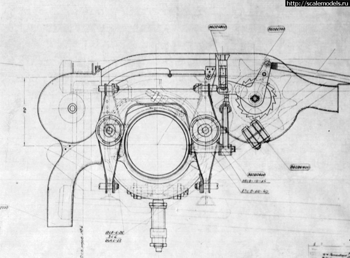
Diagram of the connection of the right wing ShVAK to its feeding line, seen from the front. Below, the same seen from the left.
The feeding duct comes from the fuselage, passes over the gun and entered from its right side.
Waste shells were expelled on the right side too; a duct deviated them downwards to be expelled through a slot under the wing.
Images from Scalemodels.ru
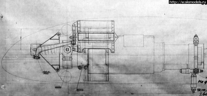
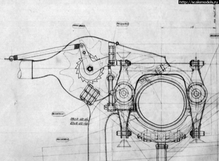
Diagram of the connection of the left wing ShVAK to its feeding line, seen from the front.
The feeding duct comes from the fuselage and entered from its right side.
Waste shells were expelled on the right side too; a duct deviated them downwards to be expelled through a slot under the wing.
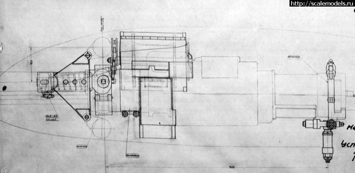
Images from Scalemodels.ru
Left:
detail of the top of the nose of a Type 17 with open engine cowling.
At the center of the image, we see the square hatch for feeding the wing ShVAK, that was left accessible by a square cut when the cowling was installed. This was common to types 12, 27, 28.
Other visible detail include the synchronized ShKAS, the supercharger intake and a cylinder's head.
Closer, and more visible, is the fuel refuelling hatch.
Right:
the open hatch of the ShVAK gun on the wings was slightly longer than the one of the ShKAS of the Type 5, 10, 18, 24, but the same of Type 12, 27 and 28.
It was locked with 6 locks instead of 4.
Images from Istrebitel I-16 of Maslov
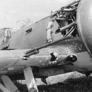
Left:
detail of the guns inspection hatch of a Type 28, that was slightly longer than those of the ShKAS-armed versions, but of the same width, and with 6 fast locks instead of 4. The photo shows also the inspection panels of the auxiliary tanks plant.
Right:
detail of the ShVAK barrel of the same plane. One can see the wide 20 mm barrel, the gas recovery tube under it, then the inverted T slot on the wing leading edge and the waste links expulsion tube, on the right side of both guns. There is an oblique lip preventing the rain from entering massively into the slot.

This drawing depicts the ammo vanes for the ShKAS on the fuselage and the locks for their doors.
The image shows faintly, in thin lines, the section of the vanes for the synchronized ShKAS and, between them, the bifurcating duct for the loading of the wing ShVAK in I-16 Type 17, 27 and 28.
The hatches under the fuselage for the ammo boxes of wing ShKAS that armed Type 5, 10, 18, 24 were preserved on ShVAK-armed versions to give better access from below for the loading.
Image from Scalemodels.ru
Berezin BS
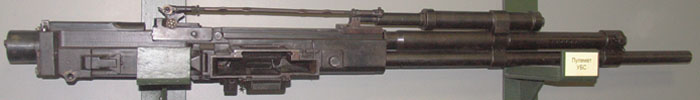
Above: UBK (left side). Below: UBS (right side).
In 1937, M. Y. Berezin designed a new 12.7 mm aircraft machine gun.
It was accepted into service in 1939 under the designation BS (Berezin Sinkhronniy, Berezin Synchronized). The weapon was good but had some defects, for example its cable-operated charging required physical strength.
In early 1941, it evolved into three improved versions:
- UBK (Krylyevoi, for the wings, charged by compressed air)
- UBS (Sinkhronniy, Synchronized, charged by compressed air)
- UBT (Turelniy, for the turret). with UBS and UBK charged by compressed air.
https://en.wikipedia.org/wiki/Berezin_UB
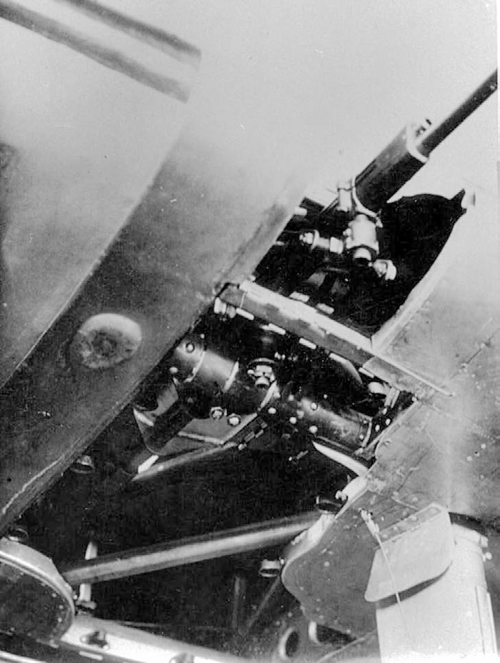
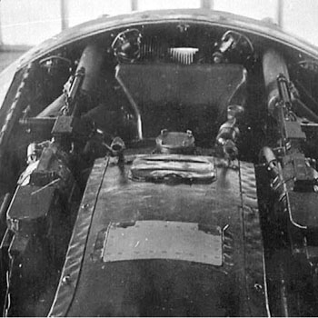
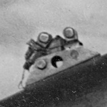
I-16 Type 29 was characterized by the synchronized BS in the lower part of the fuselage, firing through an opening on the low part of its frontal plate.
The photo shows that the weapon was reclined on its left side, feeded from above (its right side) and expelling waste shells and links below (from its left side) through two separate slots opened under a removable central blister (removed in the image) that contained the weapon.
The BS was manually armed by a cable moved from a lever on the left side of the pilot.
On the top-right corner of the image, we see also the outlet of the thin tube for the waste links expulsion of the synchronized ShKAS.
The larger oblique tube on the left of the photowas for exhaust gases from the lower right cylinder of the engine.
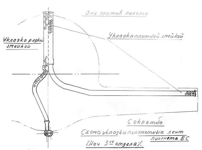
A diagram of the ammo feeding of the BS of the Type 29 viewed from the front.
The ends of the ammo belt were loaded from the hatch above the cowling inside two channels: the right one went to the machine gun in the lower part of the fuselage, the second one went into the inner section of the left wing and acted as a magazine.
(image from Scalemodels. ru)
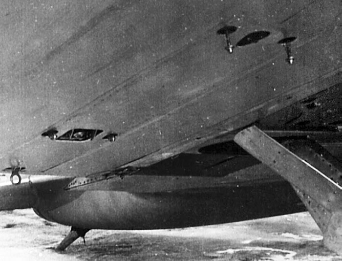
Experimental FAB-100 bombs rack
A Type 5 tested with FAB-100 bombs under the wings. Further smaller empty racks for small bombs are visible outside. This configuration didn't become a standard.
Images from Istrebitel I-16 of Maslov

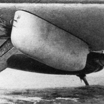
A detail of a FAB-100 bomb on the same plane.
The landing gear struts look black.
Images from Istrebitel I-16 of Maslov
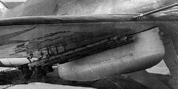
Wing armament of UTI-4b
Left: the armament of the ground attack UTI-4b.
The weapon in the wing is a UBK, the pneumatic armament cylinder over the gas cylinder is clearly visible.
The installation of the UBK was very different from that of wing ShKAS or ShVAK on I-16s. The UTI-4b had its ammo boxes in the outer consoles of wings, not in the fuselage.
The installation of rocket rails and relative reinforced skinning looks as on I-16 Type 24R and 29, while the bomb was not attacked to the auxiliary tank platem but to racks similar to those (rarely) experienced on earlier versions of I-16.
Right: A bomb and rockets unde the wing of a Type 29. It was suspended to the auxiliary tanks plate.
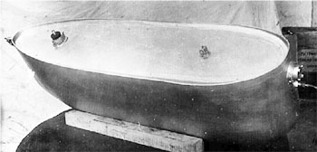
Experimental auxiliary tanks
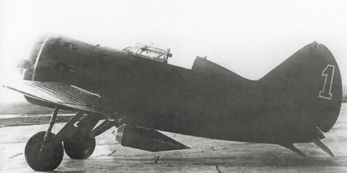
This image shows a very early Type 5 'red 1' photographed at NII VVS with an experimental droppable fuel tank in central position. This type of tank wasn't utilized on operative planes.
(image from Red Stars n.3, Gordon and Dexter)
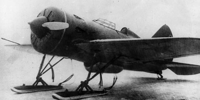
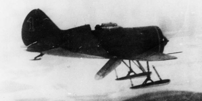
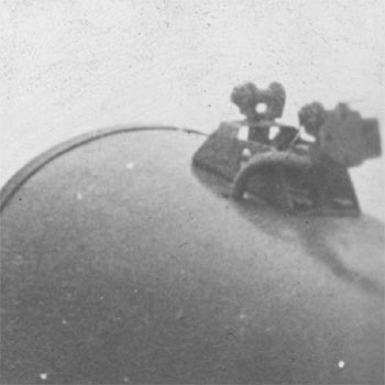
The same plane, equipped with skis, was utilized to test a conformal tank under its fuselage.
The second image shows the tank while dropping.
This type of tank wasn't deemed satisfactory and never utilized on operative planes.
Images from Istrebitel I-16 of Maslov
Standard auxiliary tanks
 Images from Istrebitel
I-16 of Maslov
Images from Istrebitel
I-16 of Maslov
Left:
A detail of the plate for the auxiliary tanks suspension that was standard on Type 20 (modified Type 10), Type 24P, Type 24R, Type 28P and Type 29, occasionally fitted on other versions too. This plate can be used for an auxiliary tank or for a bomb.
Below:
When this plate was installed, smaller hatches were installed on the upper surface of the wing consoles to give access to the system. On the photo of a Type 28, the hatch is visible close to the aileron.
The most common type of auxiliary droppable tank of I-16 could carry 93 litres of fuel and was made by compressed cardboard treated with a bonding agent.
It increased the flight endurance by 60 mins, for a loss of speed of 21 km/h.
Factories delivered six tanks for each tanks-equipped plane built.
The tanks look the same between the right and left side; so they have to be perpendicular to the wing undersurface.
Images from Istrebitel I-16 of Maslov
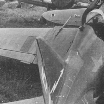
RO-82 rocket rails and RS-82 rockets
The auxiliary tanks and the rocket rails are clearly visible on this Type 29.
The rocket rails RO-82 had a tubular support, used on other types too as LaGG-3 or Yaks.
The wings were covered with a metal skinning where the fire of the rockets could have damaged the fabric skinning.
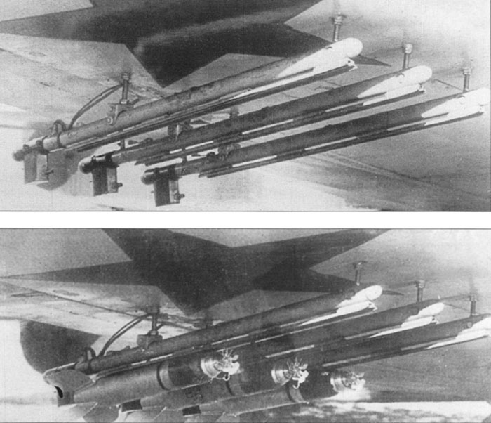
Detail of the RO-82 rails without (above) and with (below) the RS-82 rockets under the wing of a Yak-7.
Note the electric wires for the rockets ignition.
The small rotor on the front was locked by a piece of metal wire; after the launch it was free to rotate and armed the warhead.
Images from Yakovlev's piston-engined fighters of Gordon and Khazanov.
Left:
Another type of rail was possible; it was made by two L-shaped profiles joint together.
Right:
on Type 5/10 converted to ground attack planes, often only two rails (RO-82 in this case) were installed under each wing, instead of three.
The photo shows lines of rivets fixing a metal plate in the rails area to protect the fabric skinning. It is likely that an area on the leading edge was protected too, as on Type 24R and Type 29.
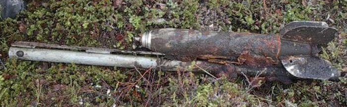
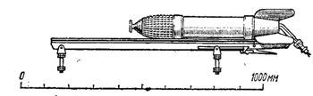
A recovered RS-82 still suspended on its RO-82 rail.
The rockt seems to have a dark green body and black winglets.
Image from scalemodels.ru
PAU-22 gun camera and its support
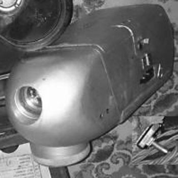
Left:
the support for PAU-22 gun camera could be installed on a support posed behind the headrest, on the back. The support, rare on early type I-16, became nearly a standard in 1940.
A plug for an electric cable actioning the camera was installed on its left side, passing through a small hole on the skinning.
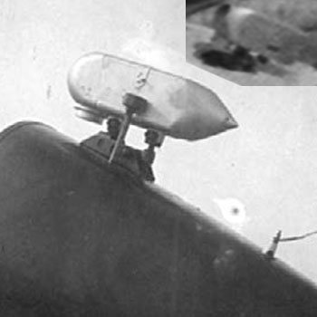
Right:
the gun camera PAU-22 on a I-16. In the small blurried detail, we see a PAU-22 from the front, installed on the wings of a I-153. The installation of the gun camera itself was much rarer than the support only.
Mid right: enlarged images of PAU-2 show a leather cover protecting it; a zip is clearly visible, starting from the front-left, probably going along all the right side and ending on the rear-left.
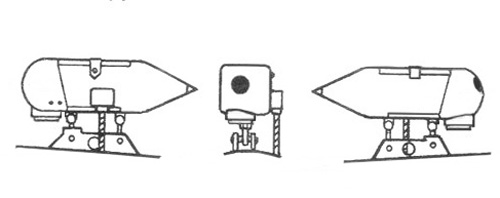
Right-down: scale drawing of PAU-22
Images from Istrebitel I-16 of Maslov
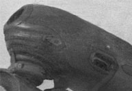
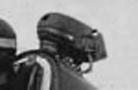
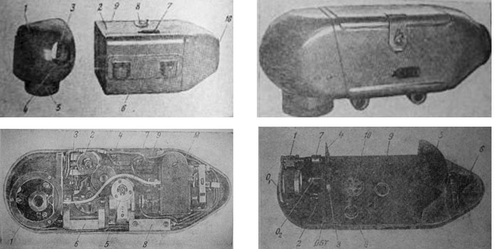
Left:
a preserved PAU-22.
Right:
images of PAU-22 from its manual
Images from Scalemodels.ru
Radio aerial mast
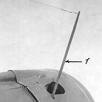
The antenna mast was introduced, as an optional, on I-16 Type 24 R, and became more common on Type 29.
The mast was easily dismountable, and was fixed on an internal support after having passed into a circular hole on the cowling panel.
Image from Scalemodels.ru