
The I-16 Type 4 entered in service with the V-VS in mid 1935, and it was immediately evident that it was a very demanding plane as flight skills for its high landing speed and its high sensitivity to controls.
Forgiving biplanes as U-2 were inadequate to learn to master this monoplane, so it was soon decided that a trainer version with dual controls was needed.
According to a source, 20 planes defined 'UTI' and 'Sparka' , factory numbers from 6211 to 62120, were built in GAZ-21 in August 1934, but it is not clear what they were.
Image from Istrebitel I-16 of Maslov
UT-2
The first two seater version was called UT-2 (not to be confused with the Yakovlev UT-2).
Three prototypes (8211 of May 1935 and two further ones, presumably 8212 and 8213). were built by GAZ-21. They were characterized by two independent cockpits under a long transparent canopy, with doors on left side only. Apart for this, and for the lack or reduction of the armament, they were very similar to the Type 4s built in Zavod 21.
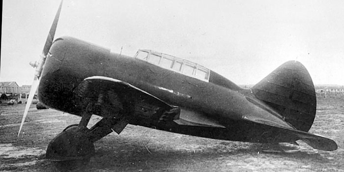
Image from Polikarpov I-16 Fighter of Gordon and Dexter
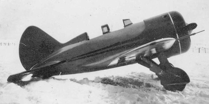
This photo shows one of the UT-2 during tests. The pilot seems Valeriy P. Chkalov.
Both the canopies and the landing gear doors have been removed for the tests.
This photo has sometimes been described as of an UTI-3, but many details point on an UT-2.
The thing in front of the windshield seems a rough aiming device; this suggests that the plane could have retained the PV-1 machine gun on the right wing similarly to the later UTI-3, differently from production UTI-2.
The plane could be painted in uniform red, including the landing gear.
Image from Istrebitel I-16 of Maslov
UTI-2
The first production training version, called UTI-2, were simpler and cheaper than the UT-2: they had open separated cockpits, with enlarged openings but no doors, no armament and no gunsight.
19 planes (serials from 8214 to 82122) were built in 1935, and production continued in 1936 up to serial 821613, but it looks unlikely that more than 600 were built. Yefim Gordon states that 57 were built between 1935 and 1936 (this would be broadly consistent with a final serial of 82163), plus forty of fifty in 1937, when the production of the engine M-22 was stopped.
Many sources, and probably the VVS itself, name the UTI-2 as 'Type 14', (probably for the apposition of the prefix 1 to the Type 4 to which it was related, just as the UTI-4 was known as Type 15 for the apposition of 1 before the Type 5 to which it was related) but the factory codes suggest that it should be called Type 8 instead.
Unfortunately all the photos of UTI-2 available represent two or three planes only, of which the best ones were taken at the NII-VVS in 1937 when the type was abandoned because of the unavailability of the M-22 engine decided to standardize all I-16 variants on the M-25. A comparison to the contemporary fighter types and to its successor UTI-4 allows a reconstruction of its look.
Image from Istrebitel I-16 of Maslov
UTI-2 of 1935

The reconstruction of the early UTI-2 of 1935 was made on the base of the drawings of the books of Maslov, of the photo of a wreck in 1941 and for analogy with the contemporary UTI-4, I-16 Type 4 and of the later and better photographed UTI-2 of 1936.
When compared to the I-16 Type 4, early UTI-2 differs for:
- being a two seater with double commands and open cockpits;
- being not armed, without aiming device or hatches to access the weapons;
- having the lower part of the engine cowling a bit more extended rearward, being not the ammo hatches under the fuselage to let accessible;
- having one fuel refueling hatch in front of the windshield, instead of two.
When compared to the early UTI-4, a successive training version based on the I-16 Type 5, it differs for:
- engine M-22 instead of M-25;
- NACA cowling, approximately cylindrical and opened on the front;
- two holes on the front of the NACA as air intakes;
- V-22 fixed pitch propeller turning clockwise, no spinner;
- no visible exhaust tubes; on late UTI-2, a single small pipe could be visible under the fuselage;
- probably a small bulge on the upper left part of the tail cone, present on type 4 only, not on successive types;
- tail fin twisted of 2° to the right to compensate the torque of the propeller, that turned clockwise (the fin of all successive versions was twisted 2° to the left, and their propeller turned counter-clockwise);
- long ailerons, each with 4 protruding hinges on the lower surface, and visible gap between wings and ailerons that disappeared on all successive versions;
- both windshields and headrests are as those of early UTI-4 (but not of the late ones);
- the top of the back was angular as on early UTI-4 (but not the late ones);
- the landing gear legs had splined-type shock adsorbers, as on early and mid UTI-4 (but not the late ones);
- it had 100x750 mm wheels (as on early UTI-4) and not 150x750 mm wheels as on mid and late production UTI-4, introduced in spring 1937.
The landing gear are represented as retractable, but it is likely that they were fixed in outer position, with the doors on the legs removed.
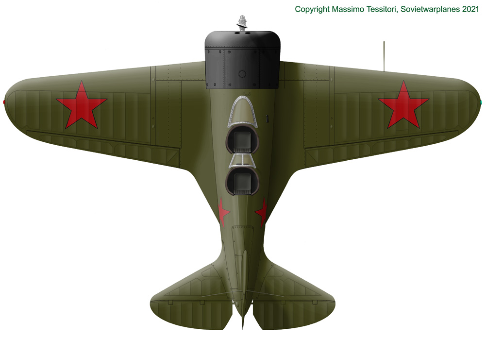
Above: top view of the early UTI-2. We can see:
- the early type wings and ailerons,
- the lack of machine guns and their hatches;
- the NACA cowling;
- the open cockpits;
- the angular back;
- the fin turned on the right of 2°;
- probably the small fairing on the left of the tail cone as Type 4.
Below: bottom view of early UTI-2. We can note:
- the protruding hinges of the ailerons and their wide gap to the wings;
- the lack of the hatches for ammo boxes behind the cowling;
- the lack of waste cartridges expulsion slots under the wings;
- the cowling ending not far from the landing gear, longer than that of Type 4.
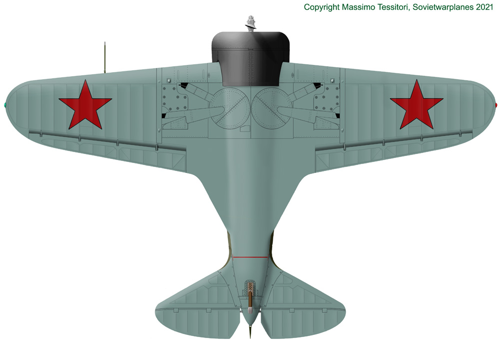
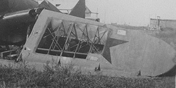
Photo of the wing console of a Type 4 wrecked during Barbarossa. The hinges of the ailerons and the wide space between wing and ailerons are clearly visible.
The UTI-2 of 1935 utilized the same type of wing consoles.
UTI-2 of 1936
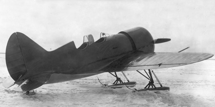
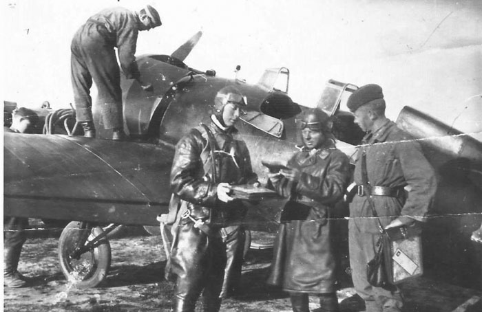
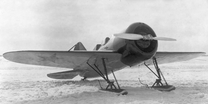
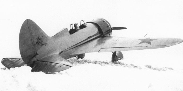
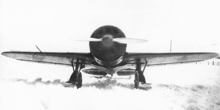
Right: photos of a late production UTI-2, tested by the NII-VVS in winter 1936/37 with fixed ski gear.
The photo shows that the late production planes (from 1936?) had wing consoles and ailerons as those of the I-16 Type 5 of 1936, while the early production planes of 1935 had hinges protruding below the wings, just as I-16 Type 4.
The plane looks to have a non-standard analogic instrument suspended inside the front windshield just for the test session.
The hinges of the rudder are covered only by two small plates, as on the UTI-4, Type 5 and later models. The fin has to be strenghtened inside, because the wiring visible on photos of Type 4 were abandoned.
The oblique cut of the black area behind the prop blade is noteworthy.
Image courtesy: Andrey Averin
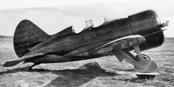
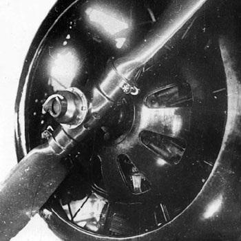
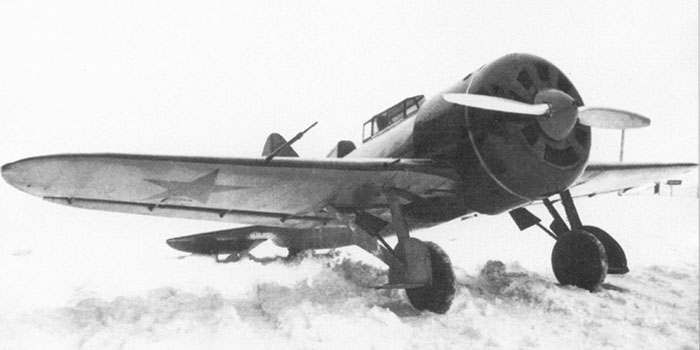
Another sharp image of the same plane. The closed landing gear bays are noteworthy.
The hinges of the ailerons were flush as on Type 5 of 1936.
The red stars under the wings are visible, so they should be on the upper surfaces too. The engine cowling was clearly black.
Image courtesy: Andrey Averin
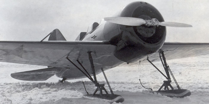
A closer version of the same image allows to see many details. The couple of holes on the top of the cowling were air intakes for the supercharger. The fixing points for the wiring of the skis are clearly visible. Note the small exhaust pipe protruding behind the cowling.
Image courtesy: Andrey Averin
Another plane, or perhaps the same one, was photographed in spring 1937 at the NII VVS. This is the most known photo of UTI-2.
This plane was there to test the landing gear retraction mechanism. According to Maslov, UTI-2 were usually flown with the landing gear locked in open position.
Image from Istrebitel I-16 of Maslov
The photos on the right show also a small exhaust pipe coming out from the cowling; this doesn't collect all the waste fumes of the engine, that were freely discharged in the cooling airflow, but only the fumes of two lower cylinders that were used to pre-heat the air for the carburetor, entering from inside of the lower part of the cooling. This preheater was common to Type 4 and UTI-2, but this is the only known photo showing protruding tubes, and it is not clear if this protrusion was of this plane only, or of all the UTI-2s, or of late production only (looks the most likely option).
Image from Istrebitel I-16 of Maslov
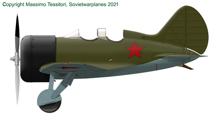

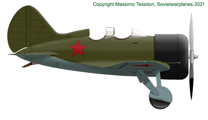
This production UTI-2 of 1936 was drawn on the base of the plane tested at the NII VVS in early 1937.
Late UTI-2s (after 1936?) differ from early ones for:
- the wings consoles and ailerons, that were similar to those of early Type 5, with hinges included in the wing thickness and less space between wings and ailerons;
- a small exhaust pipe protruding from the cowling, under the fuselage;
- the replacement of the long plate covering the hinges of the rudder with small plates as on Type 5, and the disappearing of the fastening wires that were likely installed on previous planes; despite his resemblance to the tail of the Type 5, the fin was still turned on the right as on all the M-22 engined types.
- some photos suggest that the profile of the lower rear part of the cowling could have changed between early and late UTI-2: tapered upwards for the early ones and straight for the late ones. It could also be that the factory profile was straight for both variants, and small visual differences are due to minor accidental deformations of the parts;
- at least one late UTI-2 tested at the NII VVS had its landing gear retractable and with the doors on the legs, as drawn aside.

Above: top view of late production UTI-2.
- the space between wings and ailerons was minor than on early production ones.t
- the fastening wires that were likely installed on early UTI-2 weren't installed on later ones.
Below: lower view of late UTI-2.
- The hinges were no longer protruding under the wing surfaces, and the gap to the wings was reduced;
- a small exhaust pipe protruded from the cowling.

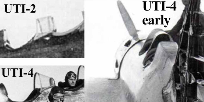
Detail images extrapolated from Type 4 and UTI-4
Despite the very few available images of UTI-2, we can have a very clear idea of it by extrapolating constructive details both from the I-16 Type 4 (images on the left: tail, engine, propeller, the early production wings) and from early UTI-4 (images below: the cockpits, windshields, the single fuel refueling cap and the flat-topped back spine, the late production wings).
Right: images from Istrebitel I-16 of Maslov.
Below: images from the web.
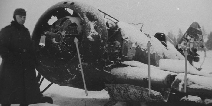
Photos of a wreck of early UTI-2
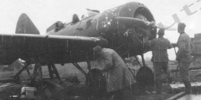
The operational service of UTI-2s was without story. Some planes were still surviving in service at the war outbreak.
Many photos are available of this type during Barbarossa, but they could all be of the same plane in an increasing state of decay.
This photo shows one, apparently still serviceable in summer 1941, when it was captured by advancing German troops.
Image from the web
It is clear that it had not exhaust pipes protruding under the fuselage.
Probably the painting was standard of the mid '30s, with dark olive green upper surfaces, medium blue-grey undersurfaces, black cowling, stars on the fuselage sides and above/below the wing surfaces. The photo seems to suggest a red cap with white outline, and a red 1 with white outline on the rudder.
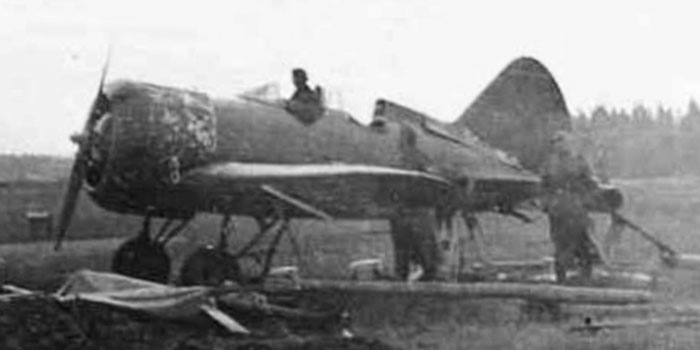
Image from the web
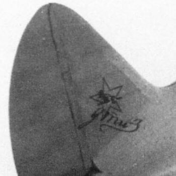
Another image, very likely of the same plane as suggested by the background and the visible damages, shows a surprising change: the tail now seems to have a light cap underlined by a dark color. What colors could give suc a change in relation to the change of filter and type of film?
A comparison to the star visible on the wing allows to exclude the use of red on the cap. So, it could be a medium blue cap with a yellow underline. Yellow often appears as black on ortochromatic films.
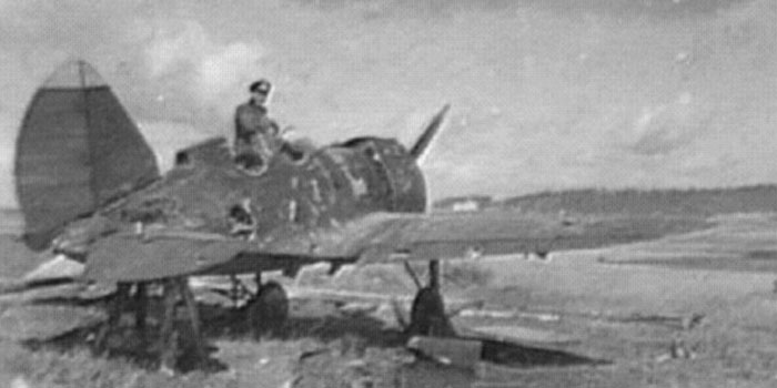
Image from the web
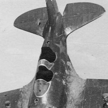
The sad plane in the sad season... although downed on the ground and badly ruined, the plane seems the same because of the hole on the fuselage.
The most important detail revealed by this image is that there was a stripe of metal covering all the slot between the fin and the rudder, just as on Type 4. It is reasonable to suppose that there were strenghtening wires between the fin and the stabilizer just as Type 4, and that this plane was representative of the production of 1935.
Image from the web
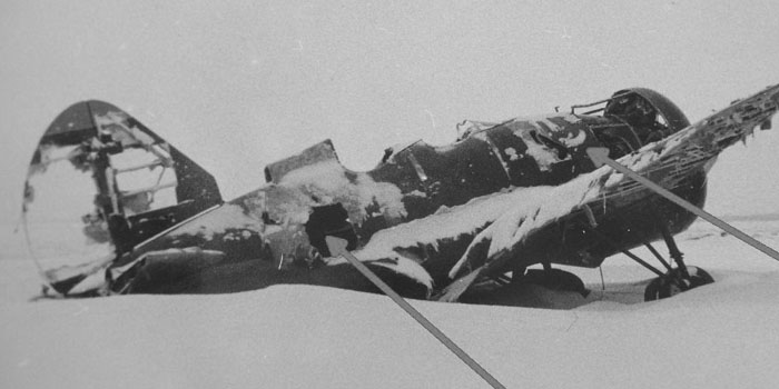
Another image of the same UTI-2 in winter 1941/42.
A protruding dark shape under the wing suggests that this plane had protruding hinges as I-16 Type 4.
Looking at the cylinders inside the cowling, one can see the 'horns' on the frontal exhaust openings of the engine M-22.
Image from the web
UTI-3
The UTI-3 was the prototype of a training version equipped with the new engine M-58.
It was built in GAZ-21 with the factory number 112111, that suggests to consider it as the I-16 Type 11.
Despite the satisfactory result of the tests, executed by the famous test pilot V. Chkalov, nor the plane, nor the engine were put into production, because it was preferred to use the M-25 for standardization reasons; so, only one prototype was built.
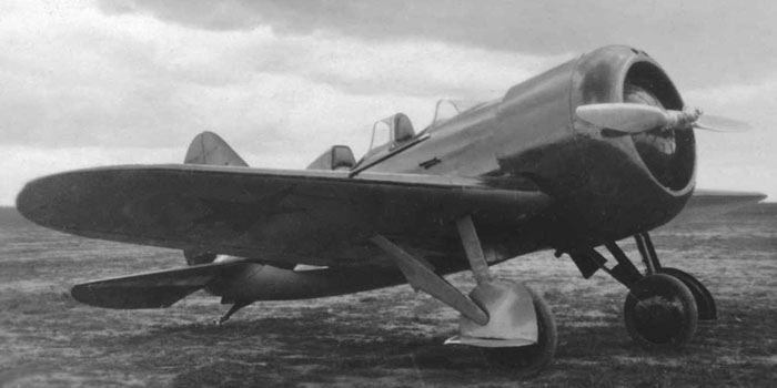
Image from Polikarpov I-16 Fighter of Gordon and Dexter
The UTI-3 had an attractive livery with a light background, perhaps a vivid color as yellow, with a dark cowling, probably black as typical of GAZ-21, and dark (red?) stripes on the sides and on the wing and stabilizers leading edges, on the frames and on the flat top of its back.
The UTI-3 still shows the Type-4 style ailerons with protruding hinges.
Note the PV-1 machine gun installed on the right wing only, firing outside the propeller's disk.
Image from Polikarpov I-16 Fighter of Gordon and Dexter
This image shows the plane tested with an enclosed cockpit, vaguely similar to that of UT-2. Probably it had the same doors on the left side.
The back top was flat as on UTI-2.
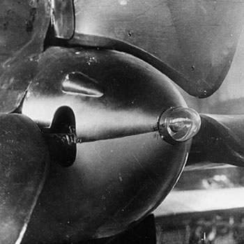
The image allows to see the position of the exhaust ports and of the vents and the small spinner that were peculiar of this prototype.
Image from Polikarpov I-16 Fighter of Gordon and Dexter
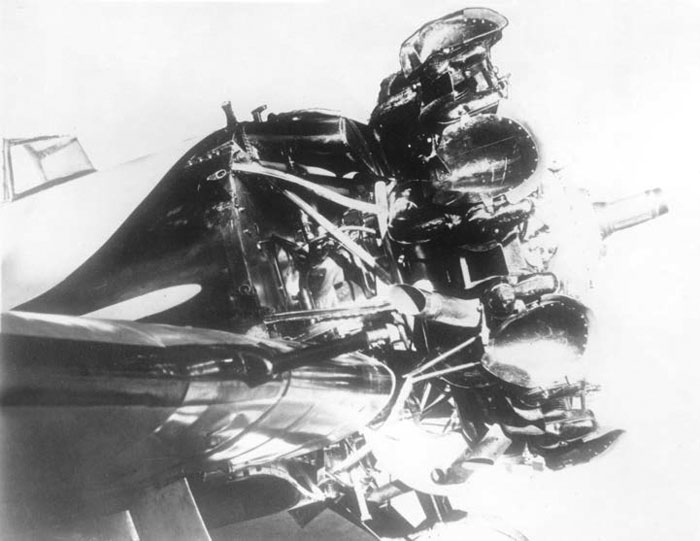
Left:
image of the engine M-58 of the UTI-3, a derivative of the M-22 that was built in few copies; the M-25 was peferred for standardization reasons.
The photo shows the barrel of the PV-1 machine gun on the right wing.
Image from Domestic aviation piston engines 1910-2009 of V. Kotelnikov