|
|
Updated on 4 June 2023
|
|
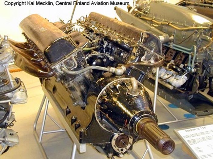
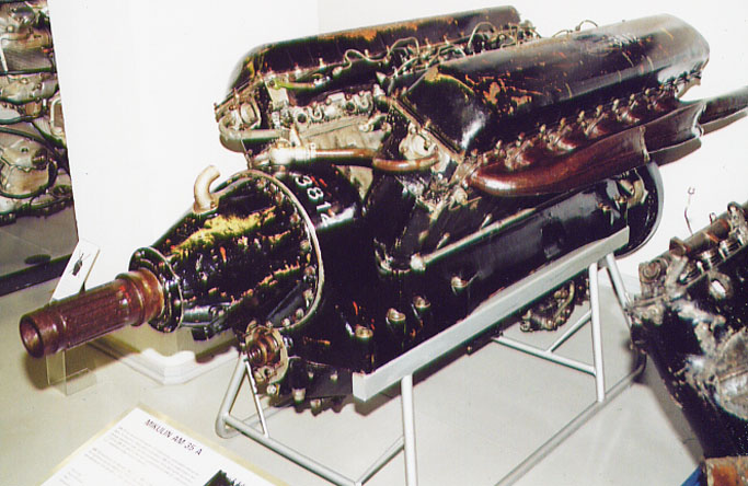
Some images of this AM-35A engine are the base of our description, in
spite of the lacking of some pieces. The most of the comments written on
this page are only deductions obtained comparing images.
The AM-35A was a 12 cylinder 60° vee engine; the max power was
of 1350 hp (993 kW); fuel consumption 330-360 g/hp for hour; the nominal
rate was 2050 rpm, while the maximum rate was 2350 rpm..
Dimensions: lenght 2402 mm, width 866 mm, height 1089 mm; mass 830
kg.
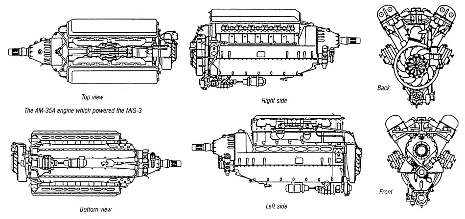
This large engine was specifically projected for high altitude use
by the chief designer Mikulin; it equipped both the single engined fighters
MiG-1, MiG-3 and the four engined bomber Petlyakov Pe-8; besides it was
used on some examples of the long range bomber Yermolaev Yer-2, as an alternative
to the Diesel engines.
This engine was very similar to the AM-38F of the Il-2 Shturmovik,
and built in the same plant (Kuybyshev, in late 1941); this was the reason
of the end of its production, and of the consequent end of the MiG-3 program
too.
Here are many detail photos, forthemost due to Kai
Mecklin, Museum Director of the Central Finland Aviation Museum.
|
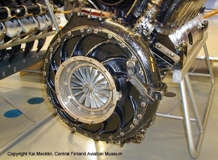
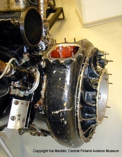
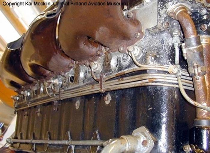
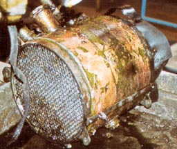
These images from behind show the centrifugal supercharger.
|
|
On this image of the supercharger, from the top, we see:
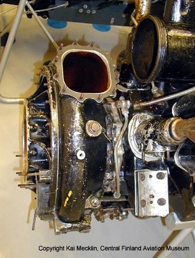
This image, from the left, shows the same things as above. |
|
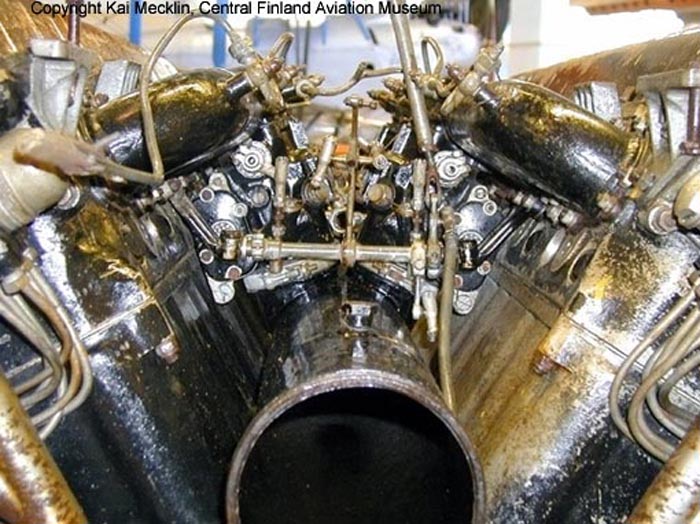
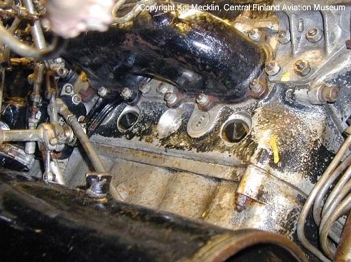
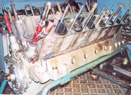
On this photo, taken from behind to thcylinder banks, we see:
|
|
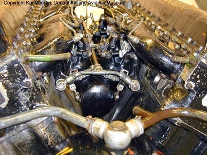
This photo represents the right cilynders bank, taken from behind-left.
We see:
|
|
Here we see the external left side of the engine.
We recognize:
|
|
This shows the engine from a frontal perspective.
We recognize:
|
|
In this frontal view we recognize:
|
|
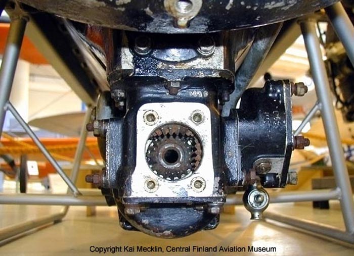
This image from the rear shows the lubrification/cooling pump under
the engine block.
We see:
|
|
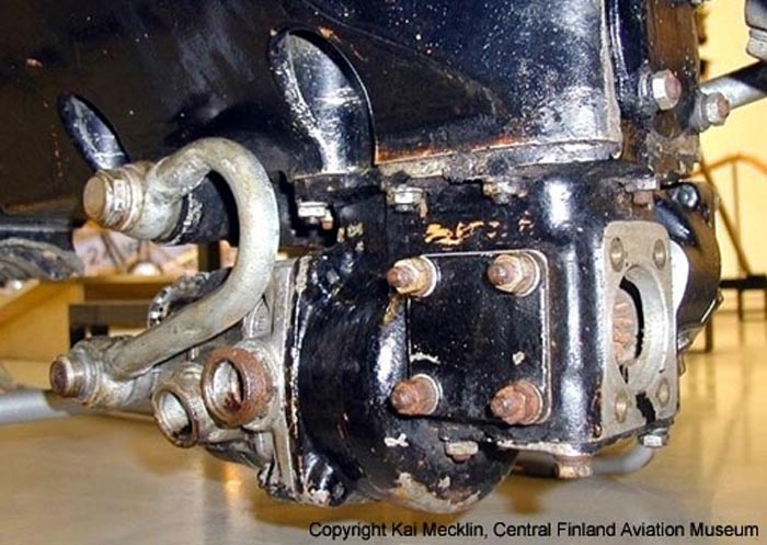
The same device seen from the left side.
We see:
|
|
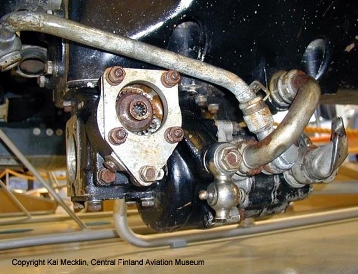
The same device seen from the right side; we see:
|
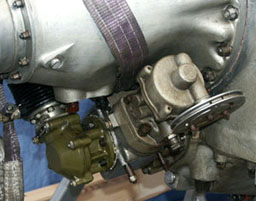 |
This image shows the pneumatic starter from an AM-38F under restoration
by Rusavia.
It should be identical to the piece missing in the Central Finland Aviation Museum engine. |
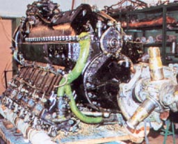 |
This image shows the AM-38F under restoration by Rusavia.
The engine is turned upside down. A green coolant pipe is visible. It should be present on AM-35A too, even if it doesn't appear on photos I have. It is likely that coolant pipes were green, and oil pipes were orange brown on original AM-35A too. Photo from Istrebitel MiG-3 by Medvedv, Hazanov, Maslov |
 |
This is the AM-38F under restoration by Rusavia.
We see the small shafts inside two red y-shaped pipes; these were for moving the distribution shafts and distributors. Probably these shafts functioned as oil pumps too. Photo from Istrebitel MiG-3 by Medvedv, Hazanov, Maslov |
 |
This is an oil cooler, again from Rusavia.
It has to be installed into the tunnels on the side of the nose. Photo from Istrebitel MiG-3 by Medvedv, Hazanov, Maslov |
|
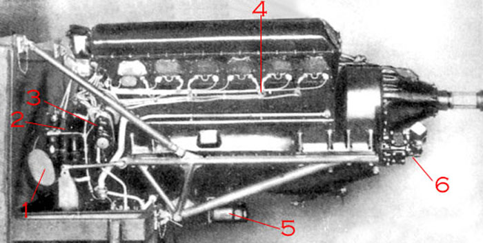
This is a complete view of the AM-35A engine.
(from MiG OKB) We see some details absent on the example of Vesiiveehma Museum:
|
|
Here we see the nearly identical AM-38F engine used on the Il-2; the
visible differences between this and AM-35A are:
|
 |
This AM-42 shows rear details; it is slightly different from the photo
above; we see:
|
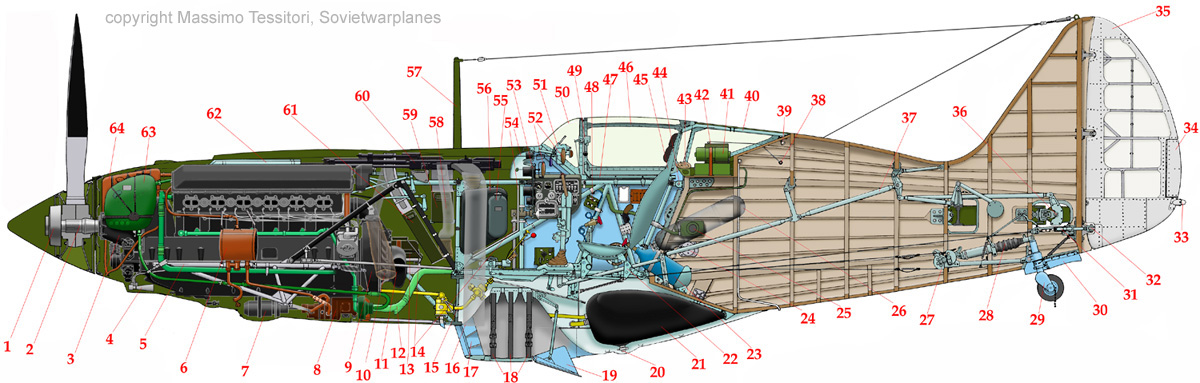
Here is a cutaway of the forward fuselage, giving a good idea of the AM-35A
engine mount.
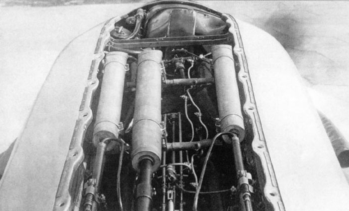
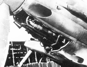
| This image shows some details of I-200 no.02, and are representative
of early MiG-3s too.
Later MiG-3s had different engine paneling. The image shows the gun barrels, enclosed within pipes to protect them from thermal shocks and distorsion. The guns are supported by two trasversal tubes, fixed to the engine. Just behind the propeller, one can see an oil tank (large, on the right) and a glycol cooler tank (small, on the left). The thin light pipes passing under the trasversal tubes are for fuel injectors. |
 |
 |
This photo shows some details of an early type MiG-3.
The larger pipe should be for coolant from the cooler to the front head of both cylinders banks (it should be splitted). Smaller pipes could be for the glycol and oil tanks. A Venturi is visible; it should be in correspondance of a small air intake on the lower engine cowling panel; it should be for some vacuum line. Note the shape of the plates mounted on the internal tube structure; the small holes are for Dzud locks, and were partially replaced by fast locks on late type MiG-3s. |