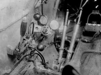
The left side of the cockpit of the Type 5 in the Chkalov Museum.
The greenish levers are for the armament of the wings machine guns.
Note that the pilot's pavement doesn't arrive up to the fuselage sides.
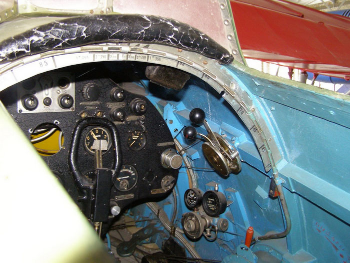
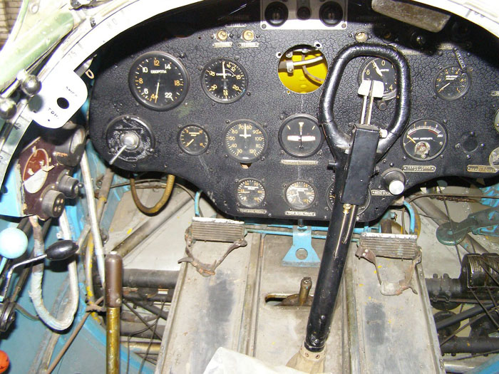
Photo of the right side of the cockpit of the Type 5 in Chkalov museum.
The metallic graduated arc on the front is an indicator of the angulation of the legs of the retractable landing gear, actioned by a crank on the left (not fully visible here) via cables.
Atop of it, we see a cushion on the front edge of the cockpit to protect the pilot's head in case of crash landing.
The door on the left side is closed and hides part of the cockpit. The early versions of the I-16 hadn't a door on the right side; it was introduced on Type 24.
The blue color of the inside probably wasn't the original one, but was painted with good accuracy during some overhauling.
Unfortunately the windshield isn't original, but obtained from an UTI-4, and is the only major flaw of this beautifully preserved Type 5.
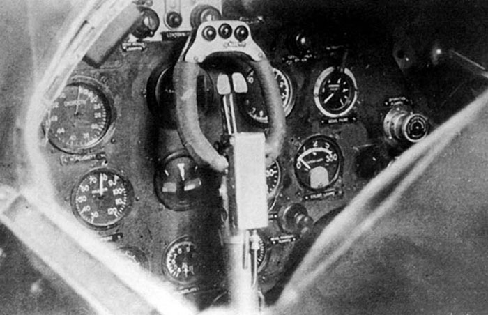
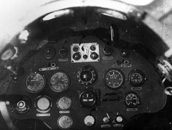
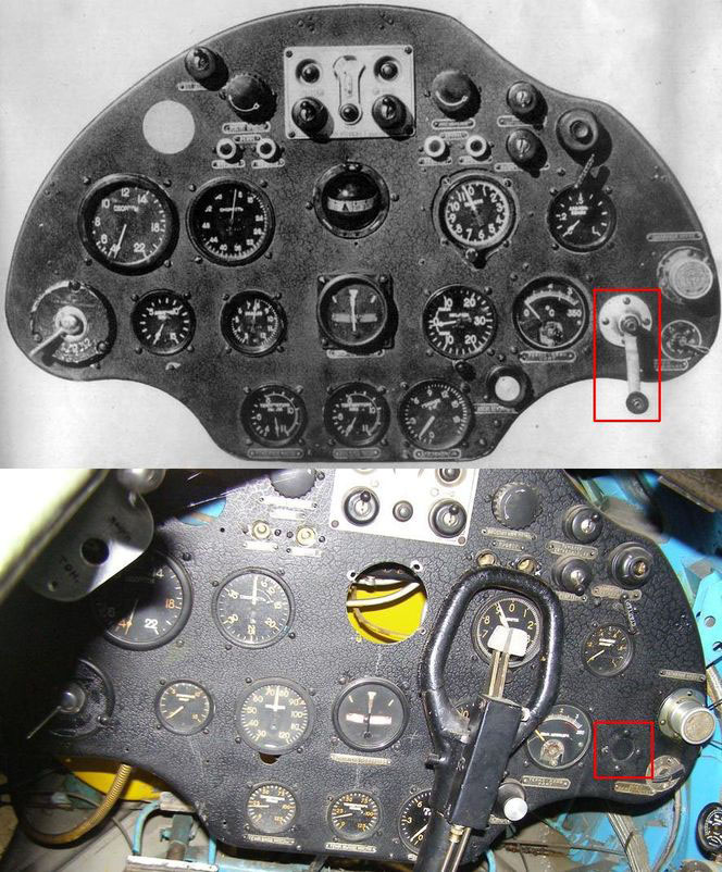
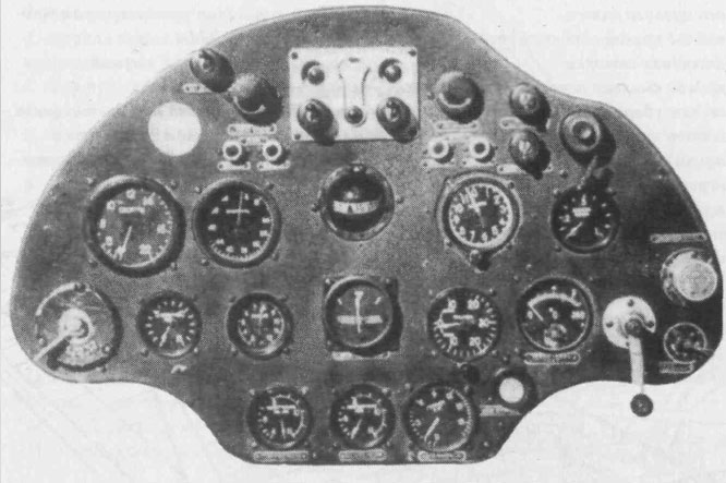
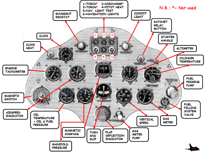
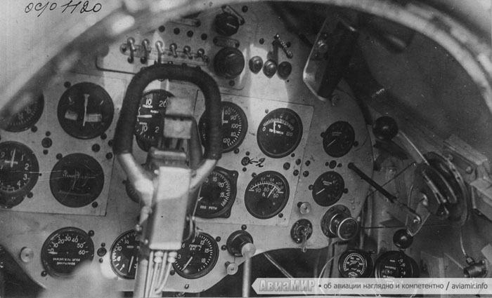
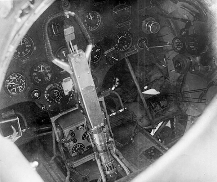
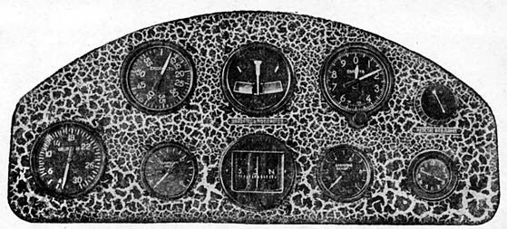
Instrument panel of I-16 captured by Finns. Although described in bibliography as Type 18, it looks more likely that the image is of IR-101, a captured Type 5 refitted with 6 rocket rails under the wings; if so, the three buttons added on the top of the cloche could be for firing rockets.
The splitting of the trigger is consistent with a Type 5, and so the visible details atop the instrument panel and the apparent absence of the handle for the armament of the synchronized machine guns introduced in later types.
Thanks to Daniele Righi for his notes
The instrument panel of Type 10.
Differently from that of Type 5, it had two symmetrical cutouts on its top.
Image commented by Daniele Righi.
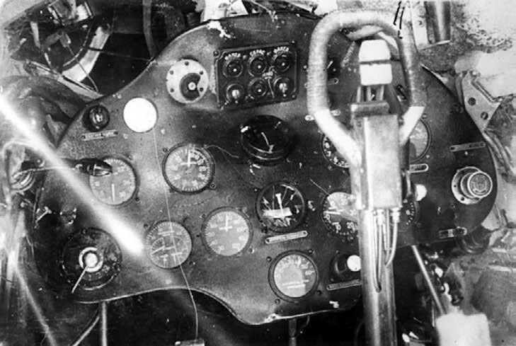
The instrument panel of the Type 10.
Note that its upper profile was different from Type 5 to allow the passage of the armament handles for the synchronized ShKAS introduced on this type and common to all later fighter versions.
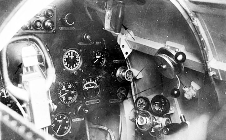
Again the Type 10.
On the top of the image, we see the armament handle for the synchronized ShKAS; another similar handle should be on the other side too.
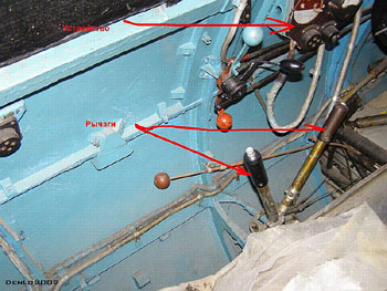
The armament levers for the wing weapons on Type 10 or 17.
The manometers and the lever on the wall are for the pneumatic actioning of the flaps, or perhaps for the pneumatic armament of the wing ShVAK.
Flaps were introduced in Type 10, and at first they were pneumatically actioned, that was somewhat dangerous because their sudden opening braked the plane; in later types (probably starting with late Type 10 or Type 18) they became mechanically actioned, so they were more gradable.
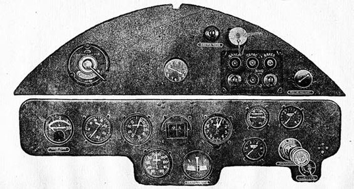
The instrument panel of Type 24 of 1940.
Compared to prevous types, one can see the presence of an electric panel at the top.
The whole instruments panel appears light (probably light grey AE-9) lacking of a thin black metal cover.
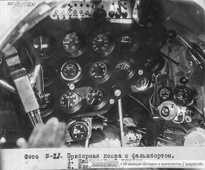
Again the instrument panel of Type 24; this plane is provided with an optional thin black metallic plate on its instrument panel.
The thing low on the right, numbered 1, is the regulator for the oxygen mask system.
http://aviamir.info/vtoroe-dykhanie-i-16/
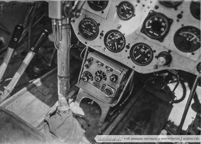
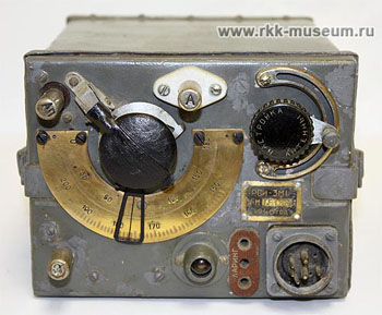
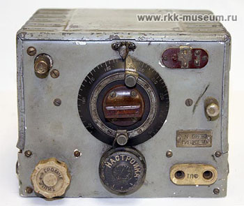
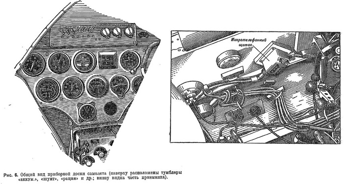
The cockpit of a radio equipped Type 24.
The RSI-3 radio is mounted under the instrument panel.
On the left, the armament levers for the wing ShKAS are visible.
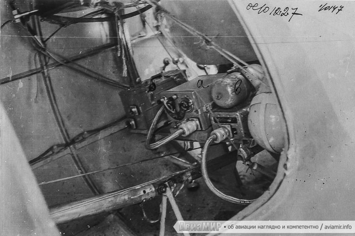
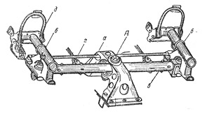
The radio system of the I-16 was located behind the pilot's seat and accessible from an hatch on the right side of the fuselage introduced in Type 24 and common to Type 28 and 29.
The letter a denotes the radio transmitter, the letter b shows the electric feeding system.
The closer thing was probably the oxygen bottle, optional given that the most part of combats during the GPW were at low altitude.
The thing below is the lever controlling the elevators.
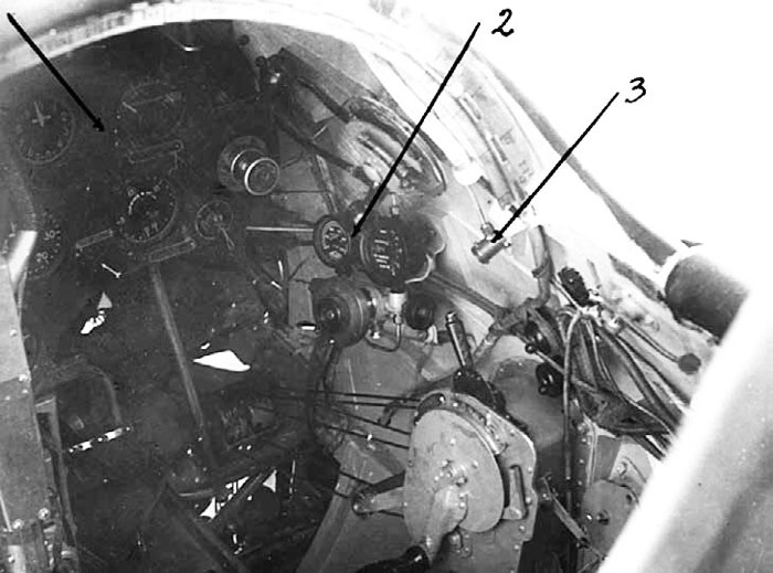
Cockpit of I-16 Type 29.
Note the radio box under the instrument panel.
An SBR-3p system for rockets release is included in the lower part of the instrument panel. This was probably common with Type 24 R.
A button looks fixed on the top of the cloche; probably this one was the rocket trigger, while the SBR-3p was to enable the modality of fire.
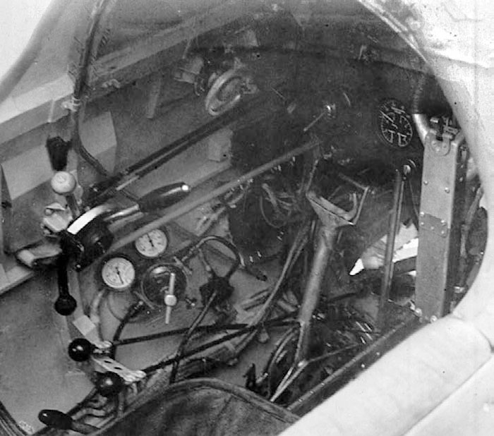
The left side of the cockpit of Type 29.
Note the prominent armament lever of the UBS, present on this type only, and the disappearing of the couple of levers for the wing weapons armament.
The right side of the cockpit of Type 29.
The crank for the retraction and extraction of the landing gear, present on all versions, is particularly well visible, as the cables directed to the legs and to the locking mechanism.
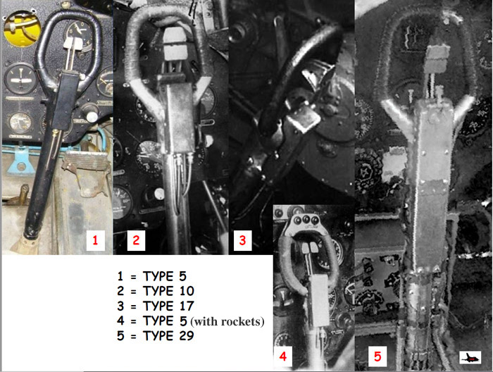
A comparison of the cloches of I-16 fighter types, that differed mainly for the triggers.
Three buttons over the lever of the type 5 could be for rockets release, as on Yak-1s, in alternative to the more sophisticated SBR-3p system.
Image commented by Daniele Righi.
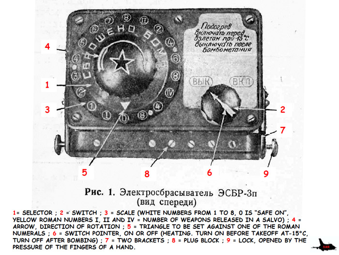
The ESBP-3p system was common to other types of rockets-armed planes as R-Z.
Image commented by Daniele Righi.
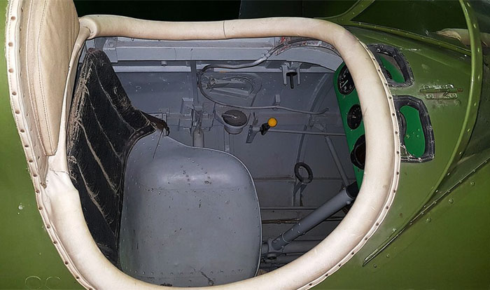
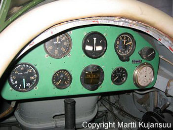
Details of the cockpits of the late production TTI-4 in Vantaa museum in Finland.
One can see that the plane was simpler than a standard I-16.
It's unclear if the emerald green color of the instrument panels reflect the original one.
The front cockpit again. Some details of the seat and pavement can be seen.
Some details are missing as the throttle.
Aside the narrow pavement, one can see the top of the wheels bays to check the landing gear extraction.
Below:
a wooden strut of the fuselage passed through the front instrument panel, that had to be splitted into an upper and a lower part. The yellow things are the fuel tan and pipes.
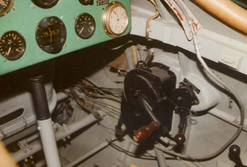
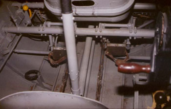
Details of the rear cockpit of the late production UTI-4 in Vantaa museum.
On the right image one can see the black crank for the retraction of the landing gear and, behind this, the lever for the control of the front shutters.
The read headrest of late UTI-4 had a rounded top, as standard I-16.
Early production UTI-4, around 1937, had a squared headrest and back spine.
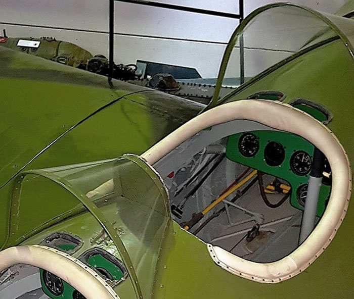
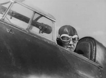
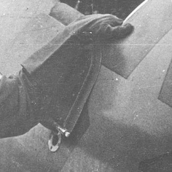
Shot of the canopy of the Type 4. It opened by sliding forward. a thing that was not so easy and quick in flight.
The left guide of the sliding canopy was partially on the door of the left side; the door could open only with the canopy fully forward. So, the most of the pilots flew with the canopy slided forward to bail out quickly if needed.
It was made with panels of glass, while the curved one atop was of bended clear plastic.
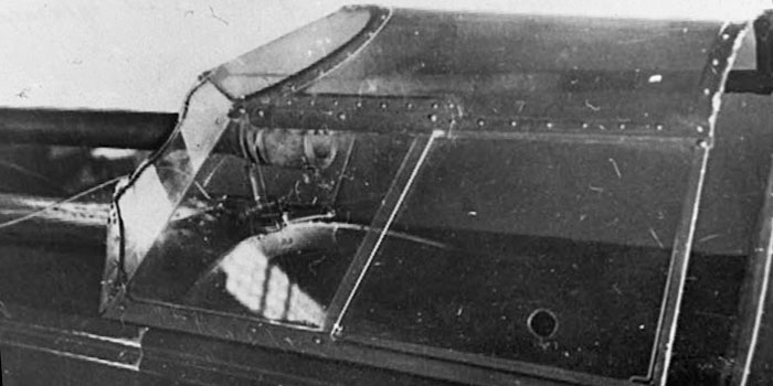
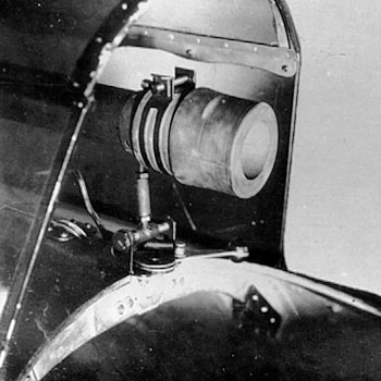
The OP-1 telescopic gunsight passed through an opening on the front; this opening was larger than the tube; on Type 5 the gap was closed by a shield, probably of rubber, solidal to the telescope, but the photos of Type 4 don't show such shield.
The transparent panel of left side was composed of two parts, the rear one could slide forward to open a window; the right side was made of one piece instead.
Just in front of the closed windshield, two small circular windows on the fuselage gave some light to the instrument panel.
Image from Istrebitel I-16 of Maslov
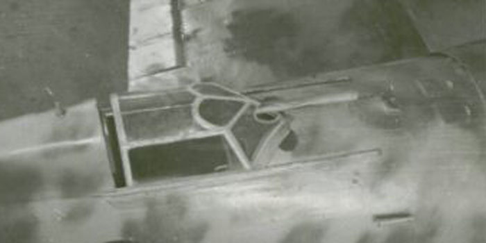
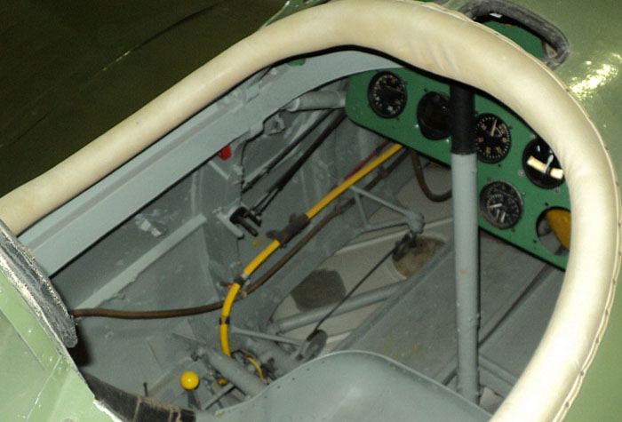
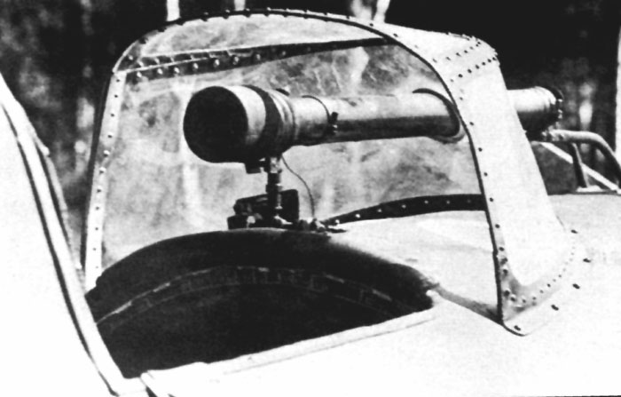
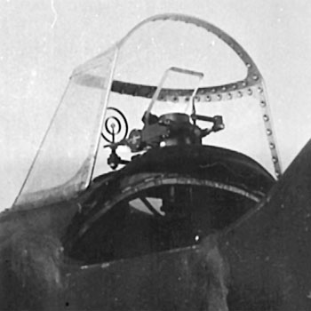
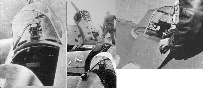
Two images of the aft-sliding canopy and of the OP-1 gunsight.
The rails on the sides and the small circular windows to make light for the instrument panel are evident too.
We see the large opening for the OP-1 and its support; when the canopy was slided off, this opening was closed by a small shield, probably of rubber; this compromised the forward visibility.
The pilots usually flew with the canopy completely slided forward in open position to have better visibility and better chances to leave the plane in case of an emergency.
The flat panels were by glass, while the curved upper one was of plastic.
Note the different shade of the plastic top in comparison to the glass flat panels.
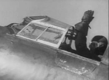
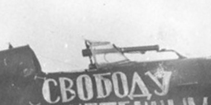
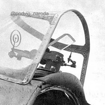
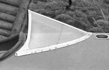
Two images of the sliding canopy of a Type 4 or 5.
The sliding canopy was usually kept open in flight for the fear to be not able to open it in case of emergency, so it was less than optimal both as visibility and drag.

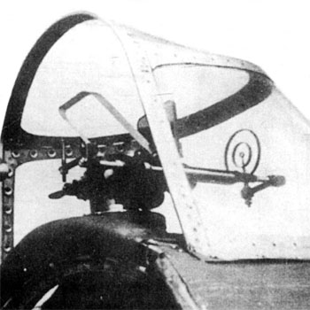
The typical sliding canopy of Type 5 was deemed unsatisfactory by pilots, that often flew keeping it in open position. So, a new fixed windshield was mounted on plane 521096, that was tested by the NII VVS (Scientific Institute of the Air Force) and deemed good, allowing a considerable improvement in visibility.
The new windshield started to be installed on production Type 5 in late 1938, at first with the old tubular OV-1 gunsight passing through the glazing.
This modification is often improperly called 'Type 6' in literature, but this name wasn't official, all their serials start by 5.....
Image from Les chasseurs Polikarpov, de Herbert Léonard
Some Type 5 with old-fashioned sliding windshield were converted to the new fixed one in a second time. Often the rails were still visible although unutilized.
In a first time, the support of the telescope mantained the shape studied for the sliding hoods, as this one. Some simpler supports ofor OP-1 can be seen on other photos.
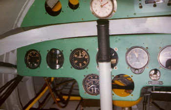
Right: photo of the new windshield with OP-1
Image from Red Stars 2 of Geust and Petrov
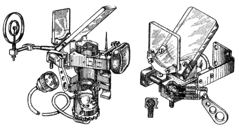
Four images of the PAK-1 gunsight.
It appeared on very late Type 5 in late 1937 and became standard from the beginnig of 1938.
In this form, it equipped the Type 10, 17, 18 and perhaps part of the Type 27.Many older Type 5 were refitted with this device.
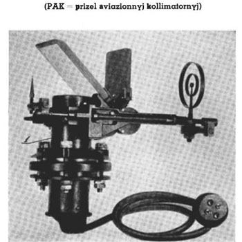
Other images of PAK-1. The reticle and the pin were linked toghether via a rod on the right side, and could be rotated downwards when not required.
The dark glass was a filter for light, it could be downed by rotating forward in horizontal position via a lever when not required.
The cylindrical body of the optic extended inside the fuselage for half of its lenghth; the flanges are to fix it to the wood skinning.
Details of the PAK-1M utilized on theType 24, 27 (late), 28, 29 and some refitted Type 5.
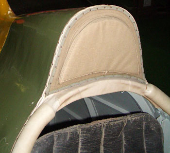
It differed for a L-shaped structure sustaining a safety cushion to protect the pilot in case of crash landings.
Note the lever on the left to raise and lower the light filter.
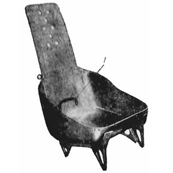

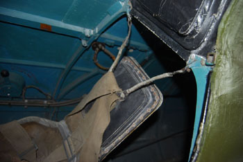
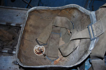
Images of the seat of the well preserved Type 5 in Chkalov Museum.
This is unarmoured.
The back belts are sustainded by a cable fixed on the headrest strut.
The lower ones, not visible here, should be connected to the outer sides of the seat and could be lying down outside the seat.
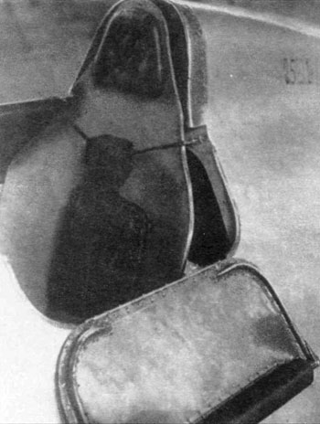
The fourth photo should be of the Type 28 in the Navy Museum of S.Petersburg ad shows something of the lower belts fixed to the outside of the seat.
.jpg)
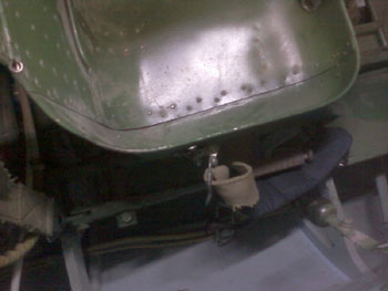
The headrest and armoured backrest of late production I-16. When the armour was installed, it replaced the light backrest of the seat, while the lower part remained.
The size and shape of the back cushion appears very different.
The upper belts are sustained by a cable, fixed on the side struts of the backrest.
A detail of a Type 29. One can see some details typical of this type (and perhaps of late Type 24):
- the door has a padding that makes it flat;
- a tissue strip cover its hinges;
- on the left fuselage side there was a plug, visible under the open door.
.jpg)
The pedals of I-16 viewer from the engine (left) and from the pilot (right). The upper arc-shaped levers were for wheel brakes, one for each side.