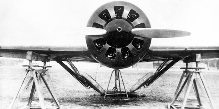
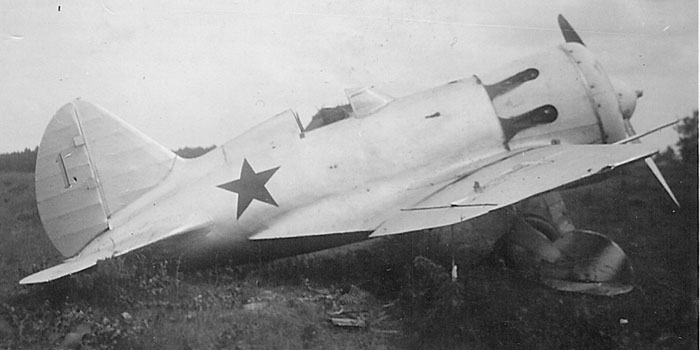
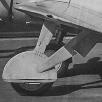
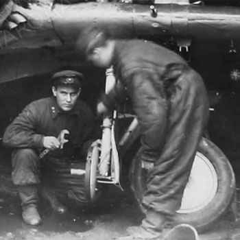
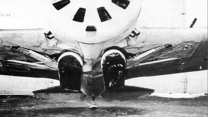
Image of TsKB-12bis in its later configuration, similar enough to I-16 Type 5, during a landing gear retraction test.
The landing gear is nearly identical to that of early production I-16s, apart for the lack of wheel covers and flaps.
Note the early 700 x 100 mm wheels, that were preserved up to early 1937, and later replaced by thicker 700 x 150 mm wheels.
Image from Istrebitel I-16 of Maslov
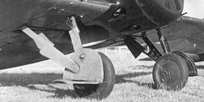
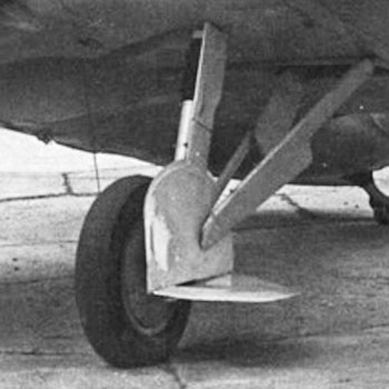
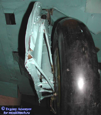
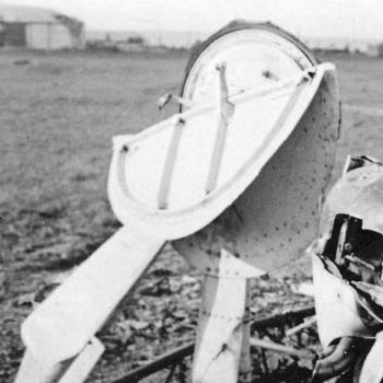
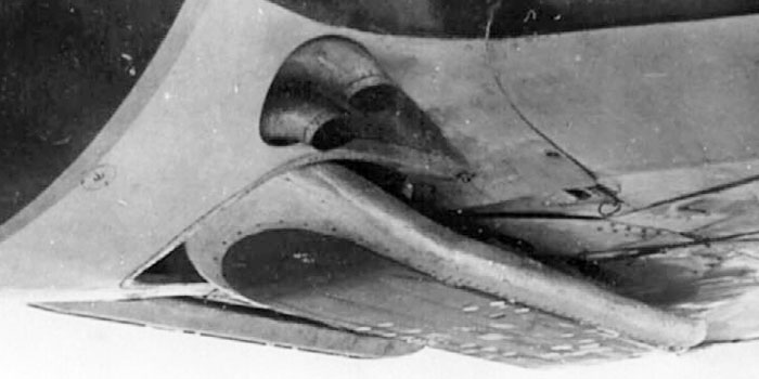
Image of the landing gear of a Type 5. The upper part of the leg cover was removed, perhaps it gave some problems.
The folding part of the wheel covers was introduced into production TsKB-12/Type4 of 1934/35 and preserved in the Type 5 of 1936/37 and in all successive versions, eventually being removed on the field in an attempt to reduce the big aerodynamic effect of the extraction of the landing gear on the plane.
The remotion of the folding flaps (and sometimes of the whole cover) was made more frequently during the war, when the modest gain in speed given by the closed covers was no longer sufficient to make of I-16 a speedy plane.
This plane is still painted in the style of 1936-37, with black cowling and medium blue-grey undersurfaces. The black color of the legs wheels, legs and inner face of covers is visible, it was common before 1938. The wheel and legs bays are painted with the same color of undersurfaces.
Image from Istrebitel I-16 of Maslov
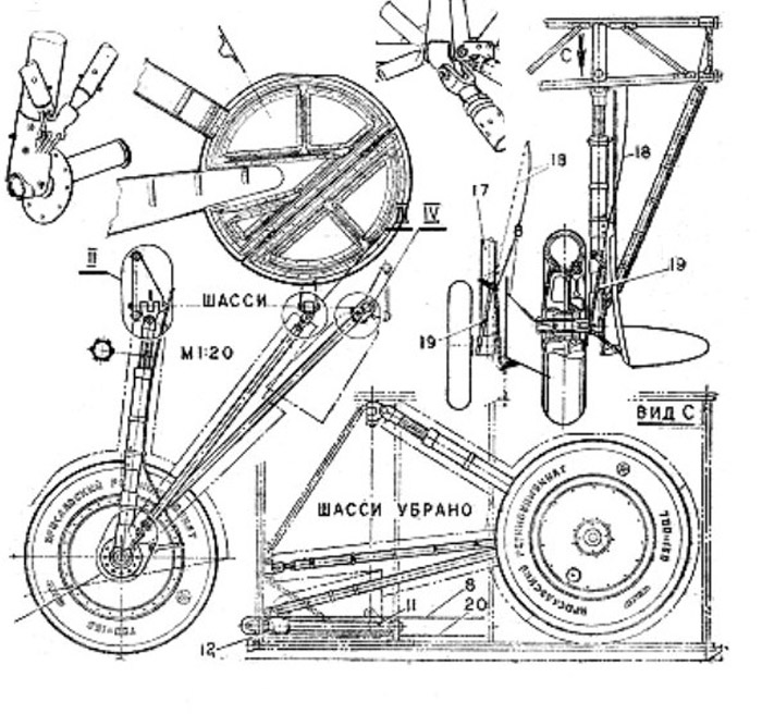
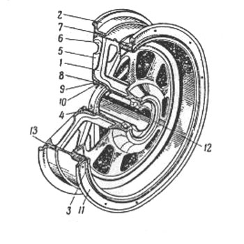
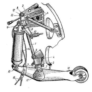
The I-16 was one of the very first monoplane fighters with cantilever wings and retractable landing gear.
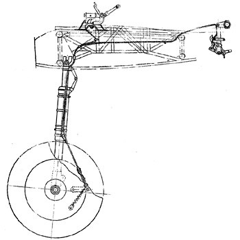
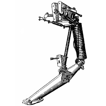
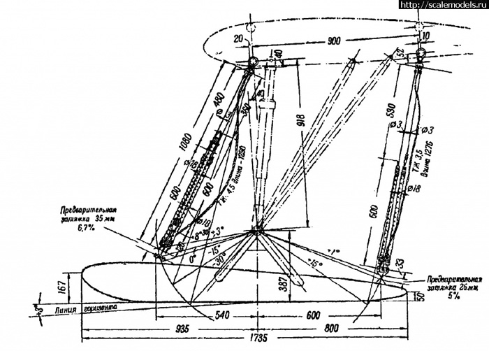
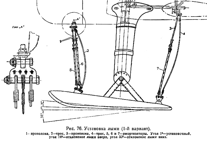
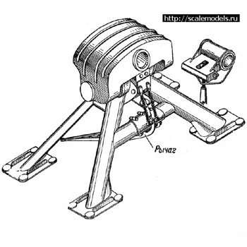
The retractable landing gear was of pyramidal type, that is it was not built by a cantilever leg supporting both bending and compression as on later planes, but the leg (17) was positioned and kept into position by two further articulated rods.
The leg retracted had a double hinge and retracted inwards and backwards; the position of the retracted wheel was moved back in comparison to the lowered one.
The base of the rear rod slided outwards during retraction.
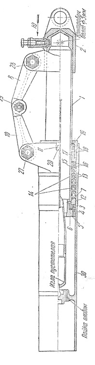
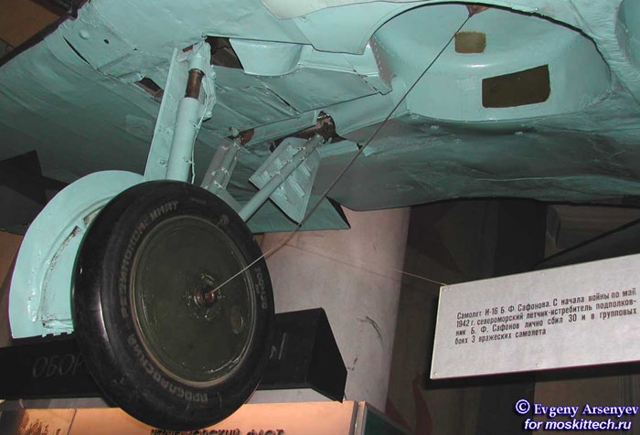
The drawing from Modelist Konstruktor represents the landing gear of a Type 5 of mid 1937, already equipped with the 700 x 150 mm wheel but still with the splined type shock adsorber.
The retraction movement of each leg was controlled by a cable controlled by a winch inside the cockpit. The cable ended in the center of the wheel pin and lifted the lower end of the leg pulling it to the bay.
The extraction movement was controlled by another cable that didn't protrude from the plane, but pull inside the sliding end of the rear rod of the gear; the combined action of this and of the weight caused the downwards movement of the gear. The sliding end was provided of a pulley, and the cable was fixed at the other end.
Below:
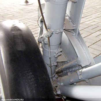
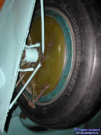
detail of the joints between the main leg and rear rods of the Type 5 in Chkalov Museum. The brake wire is visible.
Image of V.Fadeichev, Walkarounds.ru
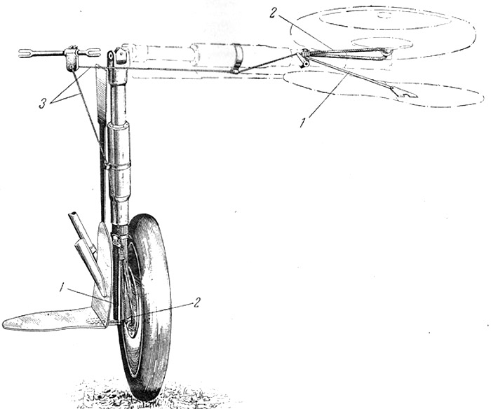
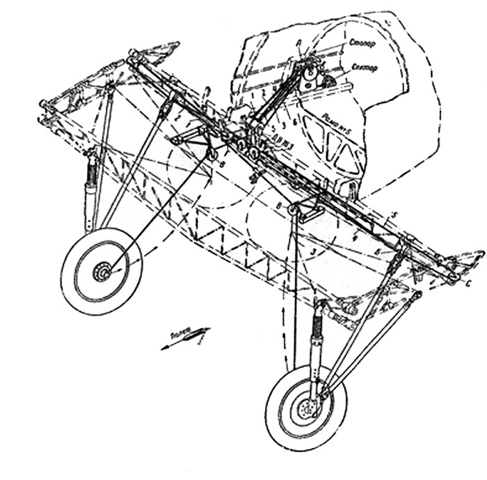
A further cable (3) was fixed under the wing surface, outside the leg, to control the movement of the wheel flap, hinged on the cover.
When in lowered position, the cable was not tensioned; a spring (2) pushed a leverism (1) that made the flap to fold 90° to the cover.
When the leg was retracted, the cable became tensioned and won the force of the spring, making the leverism close the flap.
This cable passed through a slot in the leg cover.
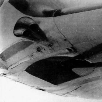
Images of the covers of the landing gear of a Type 18 (the same of Type 5-10-17-27 and similar enough to Type 4).
The main leg cover was straight and narrow, divided in two parts with a short upper one and a longer lower one that slided inside it when the shock adsorber was compressed.
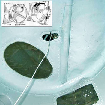
The first photo shows the cable for the wheel flap folding; it was fixed to the lower wing surface and passed through a small hole in the leg cover (that will become a long slot in later types).
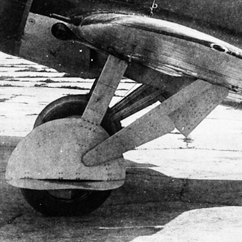
The complex shape of the folding flap cowering the wheel can be understood considering the shape of the wing/fuselage area around the wheel bay. Both the semicircular parts of the wheel cover are composed by a flat part (top-rear) that fitted to the wing surface and a cylindrical surface (front/down fitting to the fuselage, divided by an oblique line that is parallel to the flight direction when retracted.
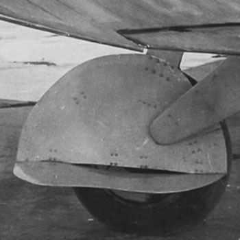
This image of a Type 5 M-25V with an unusual light grey-silver livery in 1941 shows the direction of the stain traces left by the exhaust pipes under the nose on the wheel covers. This puts into evidence the rotation of the leg: when the landing gear is retracted and the covers closed, the traces are parallel to the flight axis.
Image from the web
Splined-type legs
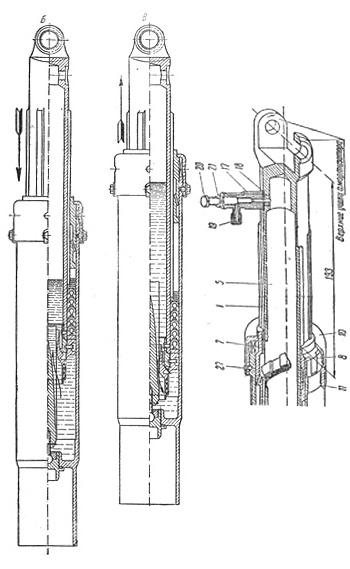
All the early and mid production types of I-16, up to 18 and 27 (excluding the 24) had splined-type main legs of the landing gear.
Left:
sections of the upper part of the main leg with the shock adsorber. A splined profile with 6 splines was intended to avoid torque of the leg. The stroke was 36 mm.
Image from Scalemodels.ru
Right:
photo of a detail of the right leg of the Type 5 preserved in the Chkalov Museum. The (rusty) splined profile is recognizable. The brownish cable is for the brake.
image V.Fadeichev, walkarounds.ru
Two details of Type 4 or TsKB-12.
Right,
the splined profile is well recognizable. Here the leg cover was omitted.
Left:
the wheel bay, with the retraction cable ending at its center. Note that the bay don't deform the rectangular hatches for the ammunition; in retracted position, the wheel and legs cover overpose to the undersurface skinning by about 15 mm, giving the false impression that the ammo hatch had a concave shape on drawings from below.
Images from Istrebitel I-16 of Maslov
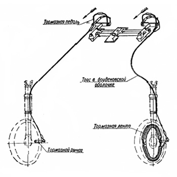
A further cable ran on the leg and reached a lever actioning the shoe brake via a cam. The brake acted on the inner surface of the wheel.
A small spring, visible under the lever, kept the brake open when not actioned.
The brake cable was actioned by the small pedals above the rudder pedals; each brake was actioned by a pedal, obtaining some directional control on the braking by differential actioning of the brakes.
On UTI-2/4 trainers (left) , the brakes were controlled both from the front and rear pedals.
Images from Scalemodels.ru
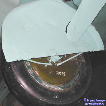
Left:
the outer wheel disk was fixed to the leg and didn't rotate; some braces to fix the wheel cover are fixed on it (blue on the photo); the brake lever, cable and spring are vaguely visible.
The outer rim of the wheel is vaguely visible; it seems that all the wheel inside was painted with emerald green as on other types of Soviet planes.
The inner wheel cover was solidal to the wheel and rotated with it.
Images from Evgeny Arsenyev, Moskittech.ru, and Scalemodels.ru
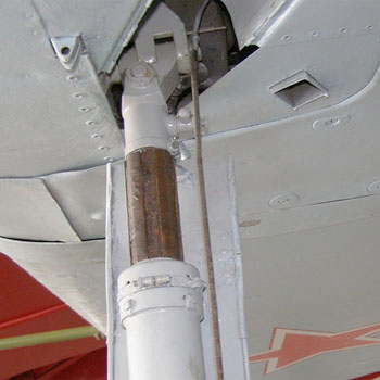
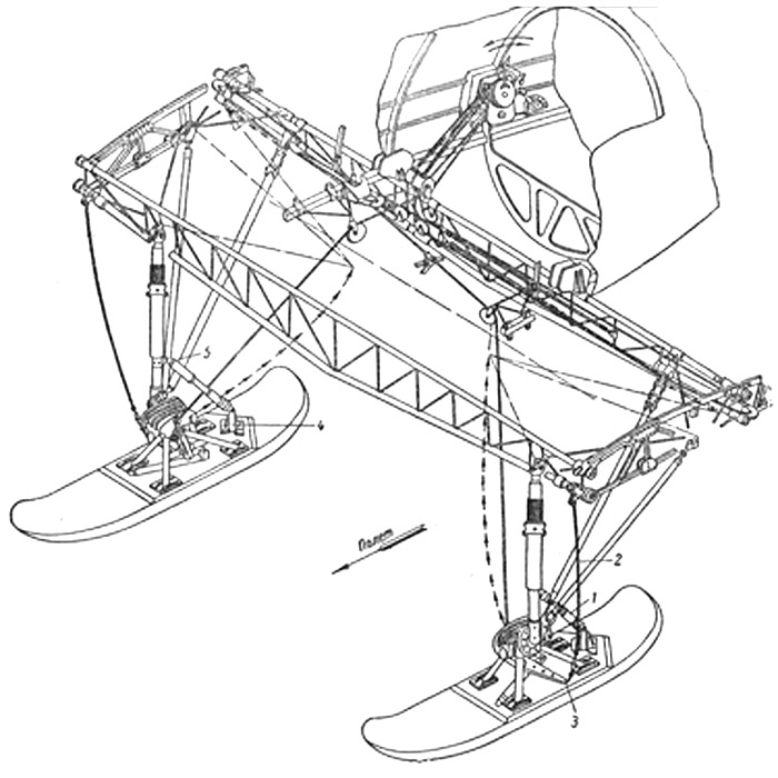
Scissor-type legs
An evolution of the original landing gear leg had a scissor-type anti-torque device instead of the splined type, and the shock adsorber stroke was increased from 36 to 96 mm.
This type of leg was first introduced on Type 24 and 28; probably it can be found on some late production Type 18 and 27 too.
It was also utilized on UTI-4, probably starting with early 1940.
A modified version of this leg was utilized on the Type 29; it was shortened by 32 mm and its stroke was reduced. This was necessary to gain space for the UBS machine gun between the wheel bays, that were moved outside of 20 mm each.
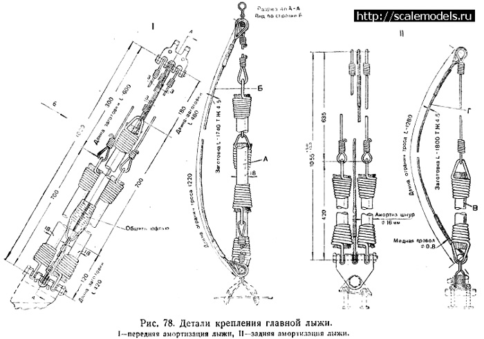
Left: the retraction system.
Center: section of the scissor-type leg and shock adsorber.
images from Scalemodels.ru.
Below:
leg of a late UTI-4 in the Finnish Air Force Museum. The shock adsorber is locked with a manifold to prevent its collapse in the long time.
Image of D.Derevyankin, Dishmodels.ru

Excellent image of the landing gear of the late UTI-4 in the Finnish Air Force Museum.
The main leg and the rear rods with their covers are well visible.
Surprisingly, two wires instead of one seem directed to the brake. It's unclear if this is a Finnish modification or what else.
The original Soviet color of the legs and inside of the bays and covers was probably the same blue of the undersurfaces.
Image of D.Derevyankin, Dishmodels.ru
The addition of the scissor required a redesign of the leg bay and of the leg cover to lodge it. The definite shape wasn't found immediately; different variants can be observed on Type 24, 28, 29 and late UTI-4 (and perhaps on late Type 18 and 27, that became progressively undistinguishable from Type 24 and 28).
Right:
the original splined-type leg of the Type 18 (and previous types) was well distinguishable for the narrow and straight cover, divided into two sliding parts of which the upper one was shorter than the lower one.
Left:
the scissor-type leg of the prototype of Type 24 led to a new design of the wheel cover and bay. The bay was extended rearwards with a niche for the scissor. The wheel cover was extended backwards, and the upper part became longer than the lower one. On the lower one, the small hole for the flaps folding cable turned into a long slot.
This shape, both of the leg cover and of the bay, wasn't definitive.
Left:
another variation of the wheel cover on a Type 24. Now the slot for the wire is on the upper part of the leg cover too; the shape of the rear edge is different. The niche on the legs bay is vaguely visible on the photo. On the leg, all the shock adsorber was covered by a flexible tubular cover.
Right:
the wheel cover of the Type 28 preserved in S. Petersburg Navy Museum has another shape. The shape of the leg bay reflects the one of its cover.

Left:
detail of the leg cover of a Type 29 was curved and with a small step between the upper and lower part.
The leg bay shape is well visible and reflects, more or less, the shape of the cover. This configuration was typical of late Type 24 and 28. The rear of the cover and bay could be a bit angulated, as seen here, or more rounded, but without an evident niche for the scissors as on early Type 24 and 28.
Left:
the legs cover of the late UTI-4 in the Finnish Air Force museum. This curved shape, with the curvature extended to the lower part, looks to have been the latest variation. The shape of the leg bay has the same shape, with continuous curvature instead of a reduced niche.
The landing gear of the Type 28 in S. Petersburg's Navy Museum shows a lot of details: the scissor behind the leg, its niche in the leg bay, the retraction cable and the brake cable. The folding flap of the wheel is omitted, and so for its cable outside the landing gear.
The wheel bay is strange, being without two nervures seen on nearly all the photos of other I-16. It's unclear if this was a variant, or is due to the restoration. The fit of the bay looks too good to suggest the replacing of the part with a non original one.
Image of Evgeny Arsenyev, Moskittech.ru
Two details of the six rods connecting the main wheel cover to the fixed disk solidal to the leg.
Again, we see the rim of the wheel painted in emerald green, probably original.
The images are from the Type 28 in S. Petersburg's museum.
Images from Evgeny Arsenyev, Moskittech.ru, and Scalemodels.ru

Two details of a photo of a I-16 Type 24 under maintenance.
Left:
the wheel was dismounted and the pin and brake are visible. The wheel flap was omitted, as often done on the field. The hinges were still there.
Right:
the wheel bay panel was dismounted to have access to the inside. The gear retraction cable was still there, and the bay panel was lowered along the cable that passed for its central hole. Two nervures are well visible both from inside and outside the bay.
Left:
detail of the nervures of the wheel flaps of a mid production I-16 with splined leg, probably Type 10. We see two transversal nervures.
According to the drawing at the beginning of the page, Type 5 had only one nervure on the flap.
Right:
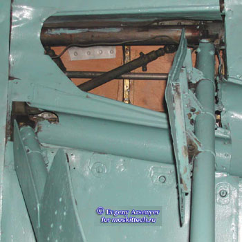
detail of the bay of the rear rod on the Type 28 in the museum of S. Petersburg. The guides of the sliding end are evident. The wood color of the inside skinning is noteworthy.
Image of Evgeny Arsenyev, Moskittech.ru
Wheel bays
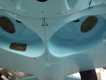
The wheel bays of the I-16 did exist in at least two variants:
the first one was typical of Type 4 and 5, and was characterized by a large kidney-shaped window closed by transparent plastic, an unique blister for a tube of the plane strut, and a rectangular window on its rear(right bay only); the central hole for the retraction cable was small and oval.
Images from Scalemodels.ru

The later one was characterized by a small square window instead of the large kidney-shaped one, two parallel nervures to give rigidity, a larger central hole for the cable with a conical protruding tissue cover; the rear rectangular window on the right bay only, not visible here, was preserved.
According to photos, the change in the style of the wheel bay was made before the change of the leg from splined to scissor type; probably it was made in 1938 with the Type 10. Wartime photos of inside the bay are rare, but photos with the dismounted bay panel are common, and allow to see the parallel nervures.
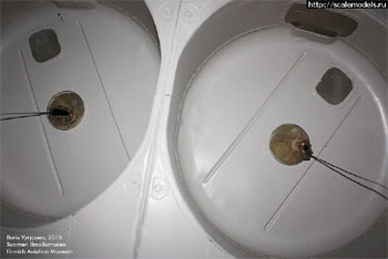
Left: the bays of the UTI-4 in Finnish AF Museum are fully representative of those of the most part of Type 10 and later. The couple of recessed nervures, the conical tissue manifold for the retraction cables, the small square windows on both bays and the large one on the rear of the right bay are recognizable.
Image of B. Vyrypaev, Scalemodels.ru
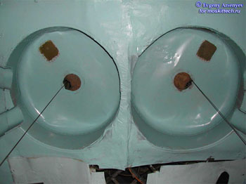
Right: the bays of the Type 28 in Leningrad is a mystery. It looks too well fitting and preserved to be a fake, but it's the only known image of late type bays where the parallel nervures are absent. Compare the preservation and fitting of the bays with the mess on the outer undersurface, badly repaired after some belly landing.
Image of Evgeny Arsenyev, Moskittech.ru
Tail skid
The tail skid of early/mid production versions of I-16 was preserved up to Type 18 and 27 (at least, to early production ones).
It was steerable, controlled by the pedals as the rudder.
Image from Scalemodels.ru
Tail wheel
The tail wheel was introduced in late 1939 on Type 24, 28, 29 and on late UTI-4; perhaps it can be found on late production Type 18 and 27, that became undistinguishable from Type 24 and 28.
The tail roller was metallic, not rubberized.
Left:
the drawing shows that it was steerable (brace 10) around a long pin 1. (image from Scalemodels.ru)
Right:
the photo shows clearly that the roller was metallic, not rubberized.
Another detail visible on the photo is the small cut on the right stabilizer's fillet for an oval maintenance hatch (not clearly recognizable on the photo) on the right side only; this hatch, absent on early/mid production types, appeared on production Type 24 and later; it is not clear if it was functionally related to the tail wheel, but this looks likely that it was related at least as a chronological correlation.
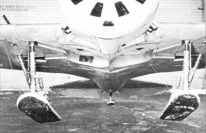
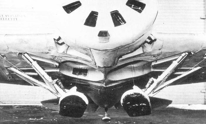
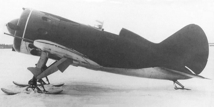
Tail ski
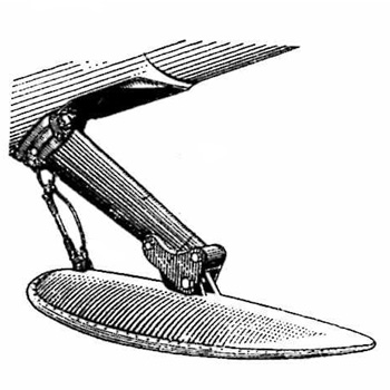
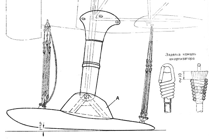
The tail wheel or skid could be replaced with a tail ski on snowy or muddy ground.
The ski had a much larger surface than the old skid, and was movable and retained in horizontal position in flight by an elastic /spring and a cable limiting its maximum downward deflection.
Image from Scalemodels.ru
Fixed ski gear
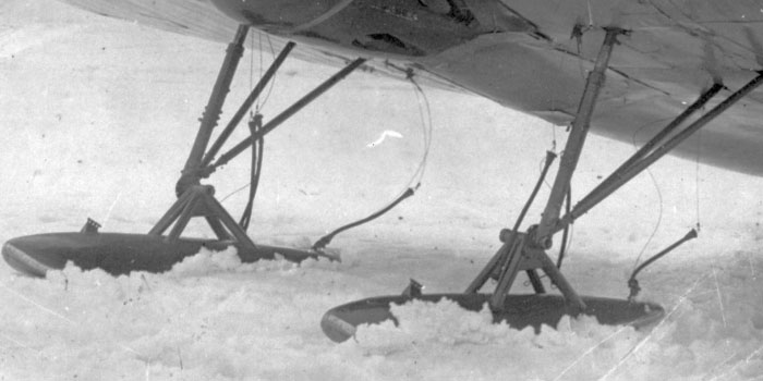
Early versions of I-16 (Type 4, Type 5, early Type 10, all the UTI-2 and 4) had the possibility to be equipped with non-retractable ski gear.
The landing gear was blocked in outer position, with its retraction, brakes and wheel flaps cables removed. The bays were closed by covers to save drag.
The skis were installed on the wheel pins; cables with springs were installing both in front and behind the ski to keep it horizontal during the flight, but allowing it to rotate to adapt to the ground when in contact with it.
On this photo, the rear wires appear joined to the ski, while the front ones are not connected; they should reach the pins on the forward part of the skis, not dangle on the legs as seen here.
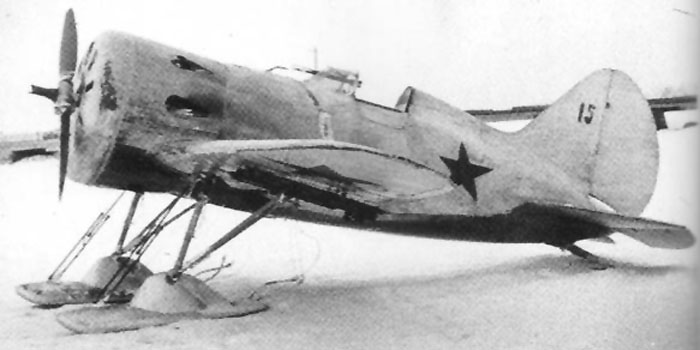
The tube strut of the skis could have been covered by an aerodynamic cover to save drag.
On the other hand, on this photo, the bays seem still open.
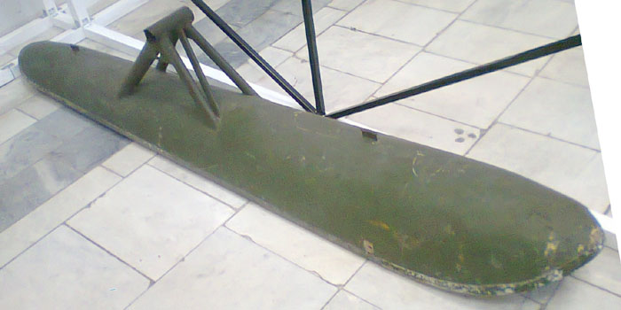
Image of a right side ski from the finnish Air Force museum
Image from Scalemodels.ru
Scale drawing of the ski and its fasteners on an I-16 or UTI-4.
Image from Scalemodels.ru
Drawings of the skis from an I-15bis allow to recognize many details common to I-16 ski installation.
Image from Scalemodels.ru
Drawings of the skis from an I-15bis allow to recognize many details common to I-16 ski installation.
Image from Scalemodels.ru
Retractable ski gear
A retractable ski installation was tested on TsKB-12 in an early stage, but it was only on the Type 17 (and on late production Type 10) that it was adopted on production I-16s.
The photo shows a late Type 10 with the retractable ski gear.
The predisposition for retractable skis required modifications to the lower part of the nose, with recesses for he ski noses that required to couple the exhaust pipes to the sides.
The retractable ski gear could be installed on Type 10 (late), 17, 18, 26, 27, 28.
It couldn't be installed on Type 29 because its side-positioned oil cooler denied the space for recesses deep enough for the skis noses; besides it was never installed on UTI-4, not even on late production ones with coupled exhaust pipes.
On this installation, the extraction cables were preserved as on wheeled configuration, while the outer cables (2) for folding of the wheels flap were modified to act on a lever (3) and maintain the skis parallel to the wings during the retraction movement.
A telescopic spring system (1) connected the leg (5) to the rear of the ski (4) to maintain it horizontal in flight, while allowing to rotate when in contact to the ground.
A detail of the retractable ski: the metallic structure connecting it to the wheel pin. It was articulated both on the pin of the wheel, both on a longitudinal axis to allow the ski rotate during the retraction movement. The brace for its rotation while retracting is visible.
During the extraction movement the tension of the cable 2 disappeared, and two springs and the ski's weight made it rotate to keep parallelism to the horizon.
Drawing from Scalemodels. ru
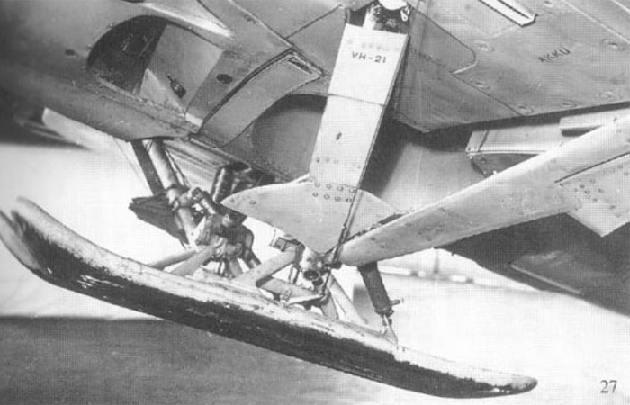
Images of the Finnish captured Type 27 VH-21 (often misdescribed as a Type 18 because its wing ShVAK were replaced with smaller machine guns in non standard installation by Finns).
On this plane, the wheel bays were left without the optional plates shown on photos below this sequence.
Images from Istrebitel I-16 of Maslov
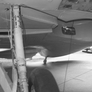
Three images of a retraction test on VH-21.
Although looking white on the photo, this plane wore the Finnish camouflage on its upper surfaces.
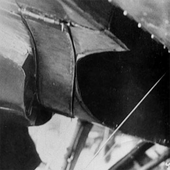
Left:
The ski in fully retracted position on a Type 17.
The function of the openings under the cowling that obliged to move the exhaust pipes aside and couple them is perfectly evident here.
Note that the vanes are not closed by the usual wheel cover, but by a smaller one not interfering with the skis rotation.
Right:
the wheel bay could have been partially closed by optional plates that let the space required for the retracted ski gear.
The legs covers could have been preserved or fully removed when the retractable ski gear was installed.
The wheel cover could have been removed, and eventually replaced with a smaller one as visible on this photo. This cover closed the gaps between the ski and the vanes without interfering with the ski rotation.
Note the tail ski for snow, much larger than the usual skid of Type 17, and articulated.
Images from Istrebitel I-16 of Maslov
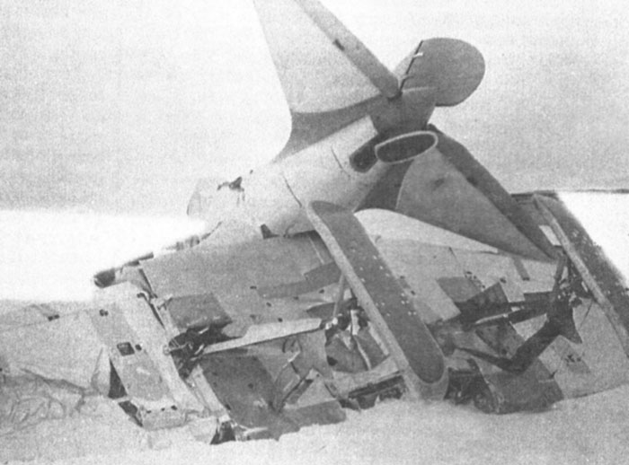
Wreck of a Type 24P (predisposed for auxiliary fuel tanks) equipped with skis after a crash.
The shape and many details of the ski gear are well visible here.
Image from Istrebitel I-16 of Maslov