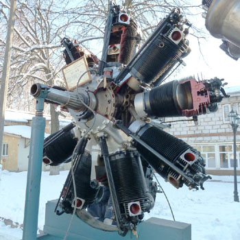
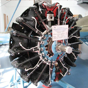
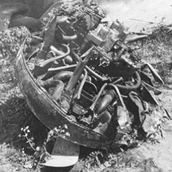
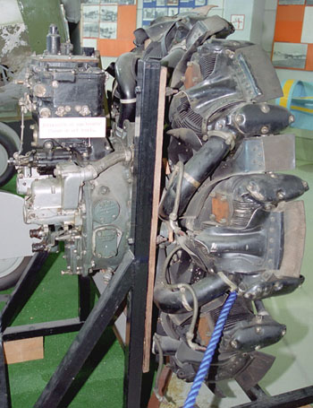
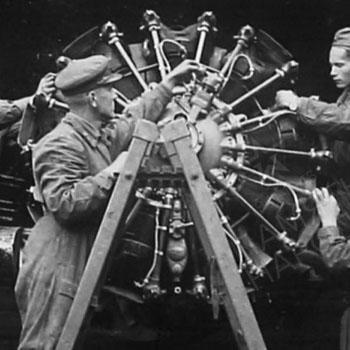
At the end of the '20s, the French Gnome-Rhone "Jupiter" VI - M-22 was licensed for production in the SSSR, after the success of the French-produced engine on the Soviet fighter I-4. The production of the so called M-22 started in GAZ 29 in Zaporozhye, after a radical modernization of that plant, and in 1930 the number of engines produced there fully covered the needs of the SU.
The mass production of the M-22 motor was a significant event in the domestic motor industry. It equipped fighters as I-4, I-5 and the first series of I-16 type 4 fighters, passenger aircraft as K-5 , STAL-3 , KhAI-1 and some others. At the end, over 3,500 M-22 engines were produced.
The M-22 was used on the very early versions of I-16 of 1934-36: Type 4, UT-2, UTI-2.
Displacement, l: 28.64
Compression ratio: 6.5
Dry weight, kg: 330
Take-off mode:-power, hp: 570 frequency of rotation, rpm: 2000
Rated mode: power on the ground, hp: 480; power at an altitude of 1,500
m, hp: 480
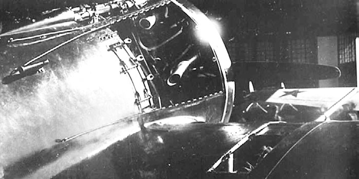
A prominent visual characteristic of this engine was that the exhaust light discharged the fumes through very short pipes on the front/side of the engine heads, and they came out from the cowling all around the fuselage, mixed to the cooling air flow. The only exceptions were two tubes on the lower part of the engine, that were longer to avoid the ingestion of fumes by the carburettor intake that was in lower position, behind the cylinders row.
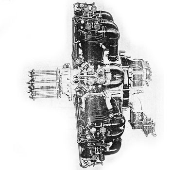
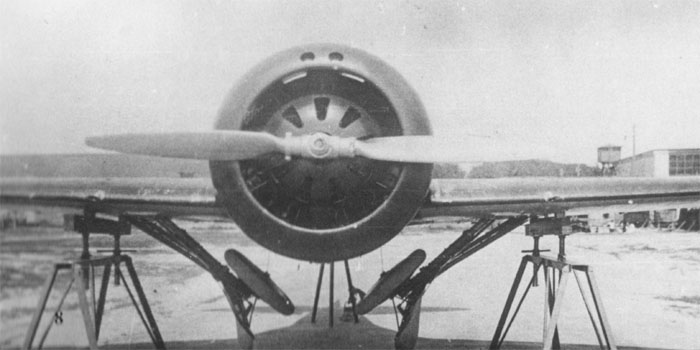
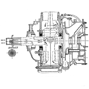
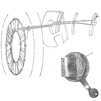
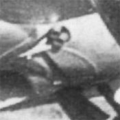
The drawing on the extreme left represents an M-22 with hjoint for a wooden propeller (not used on I-16).
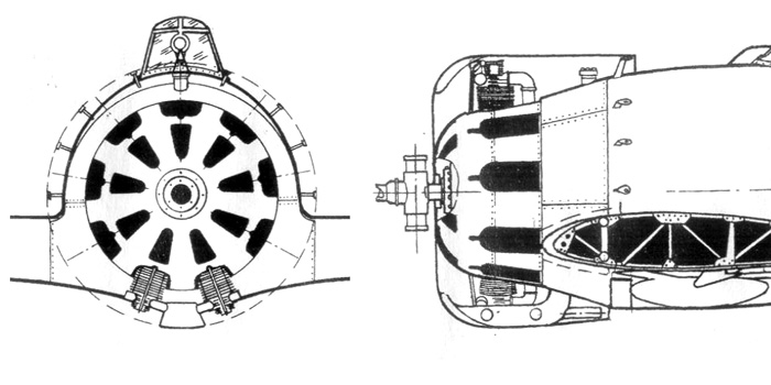
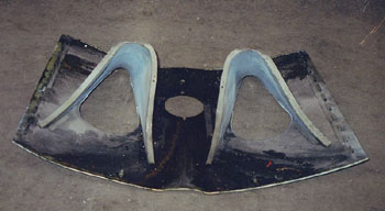
A drawing illustrating the shape of the fuselage of Type 4 under the NACA cowling.
The central part of the engine had an inner aerodynamic cowling.
Two of the exhaust pipes didn't let the gases directly into the airflow, but conducted them inside the supercharger intake and converged into one central pipe without mixing the fumes to the airflow. This acted as a pre-heating of the air flow.
All the exhaust pipes are opened inside the cowling and don't protrude from it.
Image from Istrebitel I-16 of Maslov
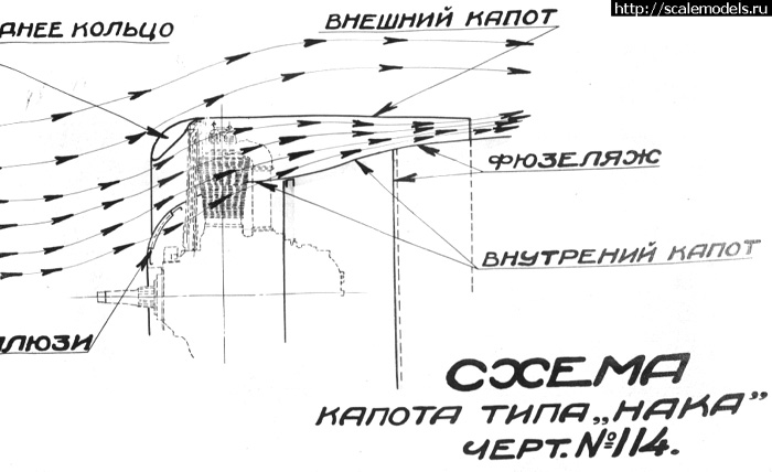
A scheme of the cooling airflow inside the naca cowling.
The main flow is guided by the aerodynamic inner cowling around the engine, passing on the outer half of the cylinders.
When more cooling was required, the shutters of the front open, and the airflow cools the vase of the cylinders.
The exhaust fumes mix to the heating airflow.
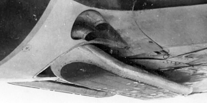
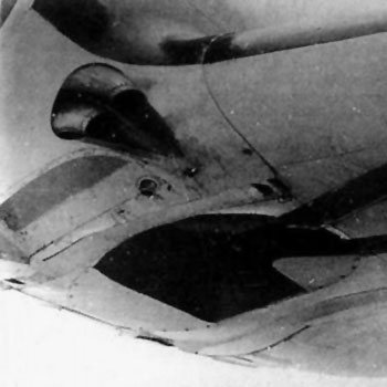
There in an inner duct inside the front ring, that brings fresh air from two holes on the upper front of the cowling downwards to the heat exchanger that preheats the air flow to the supercharger.
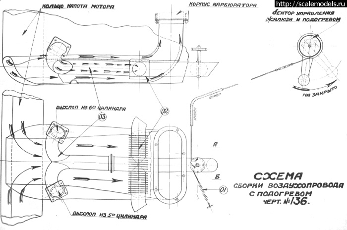
A detail of the heat exchanger to preheat the air flow to the supercharger.
One can see:
- the hollow front ring, leading the fresh air flow from the upper openings to the lower horizontal preheating duct and then upwards to the supercharger;
- two exhaust pipes from the lower central cylinders, entering into the preheating duct from the sides, joining into one pipe that divides into three parts;
- the side outlet tubes are the real heat exchangers;
- the rear tube is an outlet that doesn't contribute much to the fresh air heating, but is provided with a shutter controlled from a lever inside the cockpit; when less preheating is necessary, the shutter opens and a big part of the hot fumes flow through it, bypassing the lateral heat exchanger tubes.
Image from Scalemodels.ru
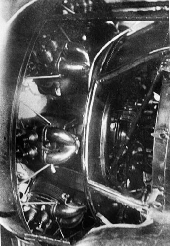
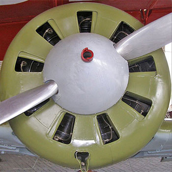
Images of the M-22 installed on a Type 4 or TsKB-12.
Left:
The intake ducts came from the centrifugal supercharger behind the row and bifurcated before entering into the cylinder's head.
The rear part of the engine was enclosed in a vane that was covered by curved plates (removed in the photo) that guided the air flow to reach the slot between the rear edge of the cowling panels (removed on the photo).
The engine itself was covered by an aerodynamic cover inside the cowling.
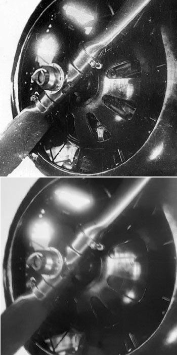
right:
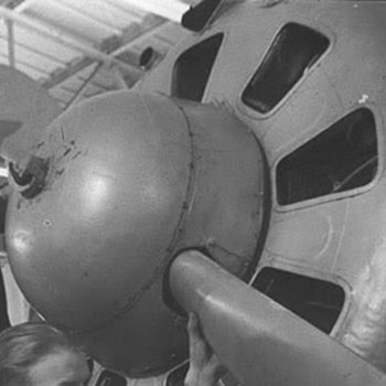
front images of the engine, that was covered by a fairing with cooling vents that cpuld be open (top image) or closed (lower image) by a rotating shutter.
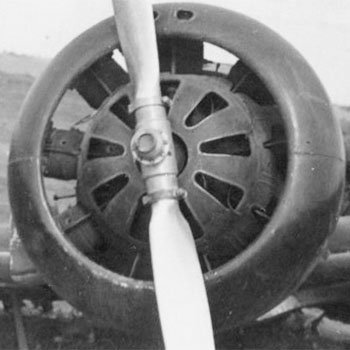
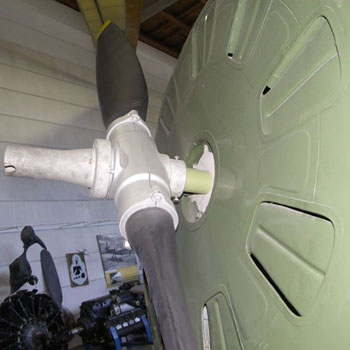
The photo shows also the hub of the fixed pitch V-22 propeller, turning clockwise from the front, differently from all the successive versions that turned counterclockwise.
Image from Istrebitel I-16 of Maslov
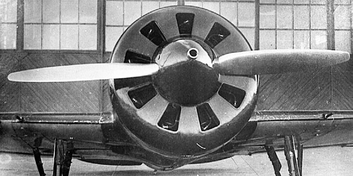
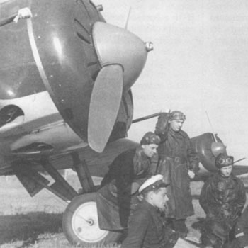
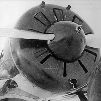
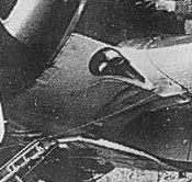
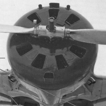
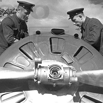
A frontal image of the plane (TsKB-12 or Type 4) shows well the front of the cowling and the V-22 propeller.
Note two holes on the top front of the cowling ring; they were not for any weapon, but for air inlet to the supercharger.
Left: Image from Istrebitel I-16 of Maslov
Right: image from Scalemodels.ru
M-25/25A engined types
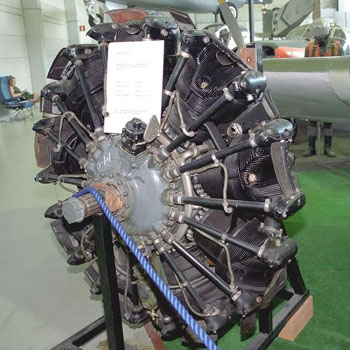
The M-25 was a licensed copy of the American Wright "Cyclone" R-1820 F3 engine; the new American engine was often referred as RCF-3 in SSSR. It offered an output of 630 hp, compared to the 480 hp of the M-22; it had also a somewhat larger diameter.
The license agreement for Wright R-1820 F-3 and technical assistance for the development of its production was concluded on April 22, 1933. GAZ 19 was established in Perm for the production of this engine in 1934.
The M-25 was an advanced and reliable design, differing from its U.S.counterpart for the use of metric standards.
The first engine, assembled from parts from the USA, went to factory tests on June 1, 1934, and passed state tests in August 1935 with a 100 hours life. During 1936, its operative life increased to 350 hours.
The start of the production was more difficult of what had been thought, and the M-25 was put into production only in October 1935. Since March 1937, engines were assembled on a conveyor belt.
A certain amount of M-25 was assembled in 1938-1939 by factory No. 27 in Kazan from sets of parts obtained from Perm. In total, before the beginning of 1942, 13888 units of M-25 of various modifications were produced.
M-25 engines were apt for high-altitude use and had a regulators of constant boost pressure, which freed the pilot from the need to manually keep the boost constant. In addition, the engine had a pressurized oil outlet on the toe of the crankshaft to control the propeller, which during take-off could be set to a small step by switching the crane. By a large step, the screw was installed by the action of centrifugal forces acting on its blades and the counterweights installed on them, when the crane was set to drain oil from the hydraulic drive of the screw. This, of course, improved the characteristics of the aircraft during take-off and climb and was the first step to the use of propellers with a variable pitch and a constant rotational speed (VHS).
Displacement, l: 29.87
Compression ratio: 6.4
Engine weight, kg: 433
Take-off mode : power, hp: 625, rotation frequency, rpm: 1950
Rated mode: power near the ground, hp: 625; power at an altitude of
2000 m, hp: 700
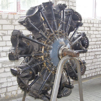
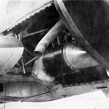
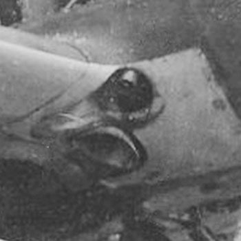
Section of the center part of an M-25. the rotation was transmitted to the prop shaft without any reduction gear.
The shaft itself had a hole that let the cooling air enter deep inside the engine.
On the rear, the centrifugal supercharger received the air from an
intake un the upper part of the engine.
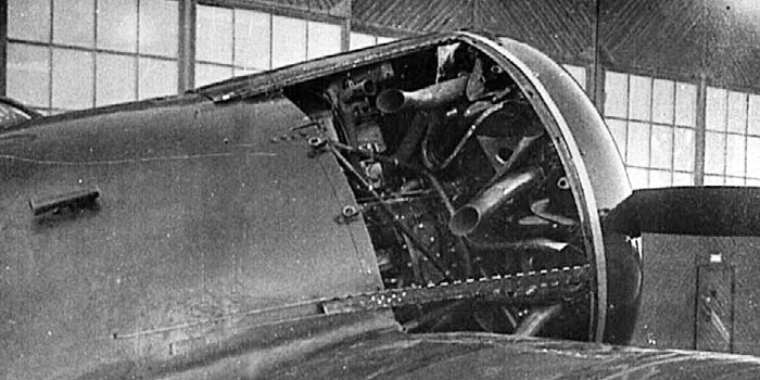
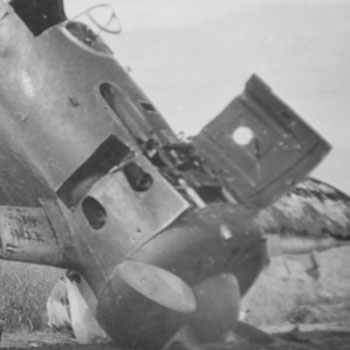
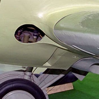
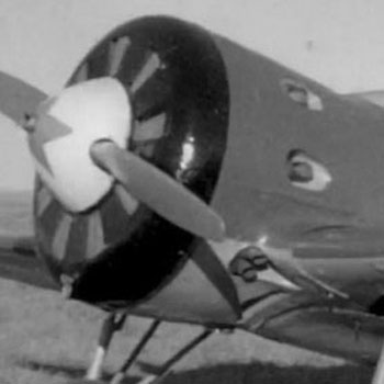
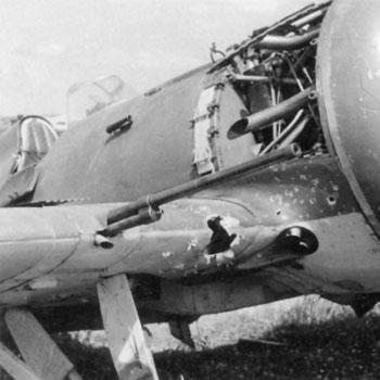
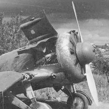
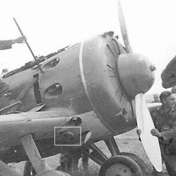
The I-16 Type 5 was based on the prototype TsKB-12 bis in its modified form after having been rebuilt after an accident: a new engine cowling was adopted, covering a new imported Wright Cyclone SGR-1820-F-3 moving an imported two blades Hamilton-Standard propeller with a spinner.
The real prototype of production Type 5 was the TsKB-12 s/n 123954, the 54th I-16 type 4 built by GAZ 39 converted to the RCF-3/M-25 engine.
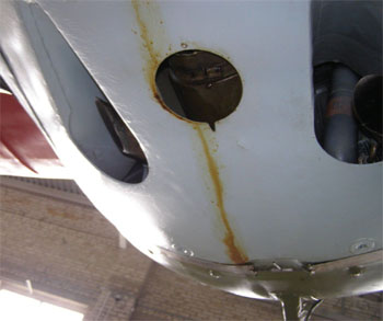
This photo of TsKB12 123954 with the open cowling shows the new configuaration of the cowling, more tapered to lodge the new engine of larger diameter and with exhaust pipes protruding from vents on the cowling sides and lower surface.
The internal fairing of the M-22 engine body was abandoned; internal guides around the exhaust pipes conveyed the most part of the cooling air around the cylinders and to the side vents.
The supercharger intake is visible behind the engine in upper position, aspiring the air passing between the upper cylinders.
The engine panels were secured both with Dzud locks (only 2 on their rear side on this plane, they'll became 3 on production planes) and by rods passing into hinges on the junction lines. The rods appear moved back; on production planes they ended with rings that were visible even with the panels in position.
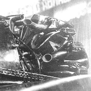
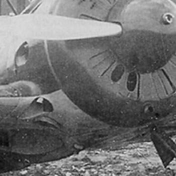
The second image on the left shows the rear-left side of an M-25 or 25A from a Type 5 wrecked during Barbarossa. The supercharger intake is visible on the top.
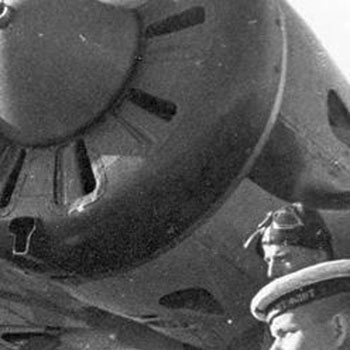
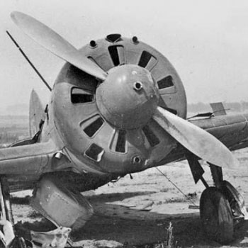
The front view shows that the front was closed with a plate with 9 vents, one in front of each cylinder. Those vents could be closed by a rotating shutter just behind the plate.
The photo shows the new spinner and the new VFSh propeller with pith adjustable only on the ground, with pointed spinner.
A manual of M-25 engined I-16 gives a diameter of 2.9 m for the propeller; this could have been true for some prototype, but the propeller installed on production I-16 had a diameter of 2.8 m. This could have to do with the typical shape of the VFSh-6 of I-16s, that show a sudden change in curvature at its tip as if it was shortened.
Note that the front plate of M-25 versions of the I-16 was very smooth, the only protrusion being the raised contours of the vents; later versions of I-16 had more protrusions.
Image from Istrebitel I-16 of Maslov
Type 5 (some)
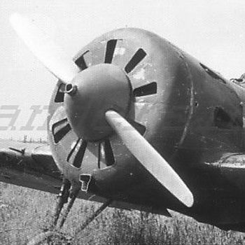
M-25V is a modification of the M-25 motor, created in 1936 and installed on I-16s starting from the end of 1937 or the beginning of 1938. It differed from the simple M-25/M-25A for its power, increased to 775 hp takeoff power and a height of 3000 m.
This engine required a larger oil cooler, that had to aspire cooling air from a (slightly asymmetrical) T-shaped air intake posed on the lower part of the front ring.
It was the typical engine of I-16 Type 10 and 17 and mid/late production UTI-4; it can be found, from the factory or as a refitting, in some Type 5s.
In 1941 an improved version, having commonality with M-62/63, was manufactured to power the late production UTI-4.
The color images are from the well-preserved Type 5 M-25V of the Chkalov Museum.
Images from Scalemodels.ru.
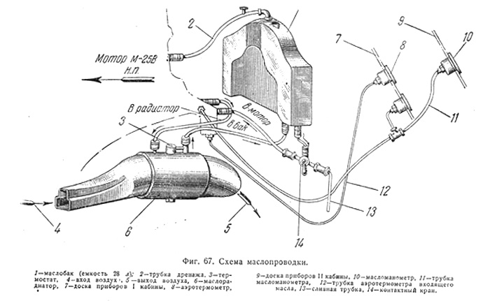
Here we see the oil circuit of M-25V from a manual.
Strangely, the section of the inlet seems different from that visible on the outside.
Image from Scalemodels. ru
A M-25V in maintenance during the war, installed on a Type 5 converted into a ground attack plane.
The holes high in the air conveyors at 11 and 13 o'clock are not for machine guns, but to allow fresh air to reach the supercharger intake behind the top cylinder.
The shape of the prop blades of the M-25 were easily distinguishable from that of the M-62 and 63 engined MV-1: it had a thinner chord (217 mm ) and a change in curvature at its tip.

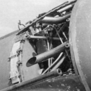
Detail of the right side of the engine, with open panel.
- Some details can be recognized;
- the prominent exhaust pipe at the center;
- 3 dzud lock bases o the left, and one (of two) on the right;
- the oil tank, the scratchy dark brown thng on the top-left;
- the yellow thin pipes, probably for fuel;
- the tubes strut, black;
- the air conveyors to the outlet vents, black, on the right;
- the supercharger, at the centre of the air/fuel mix radially directed to the cylinder's heads;
- the air-fuel feeding tubes, black with orange bands;
- the hand and beret of someone, optional.
Another detail from a more raised position. We can recognize:
- another exhaust pipe;
- the oil tank, dark brown, on the left;
- the supercharger intake, center-top, black but reflecting;
- the tubes strut to support the engine.
Further image that allows to recognize:
the exhaust pipe;
the supercharger intake, center, that aspired air passing through the top cylinders;
the oil tank, left, and the vertical short tube to refuel it through a circular hole on the top pf the cowling (not visible here);
detail of the strut and hinges to lock the longitudinal edhes of the panesl to the strut (top) by a rod inserted from behind.
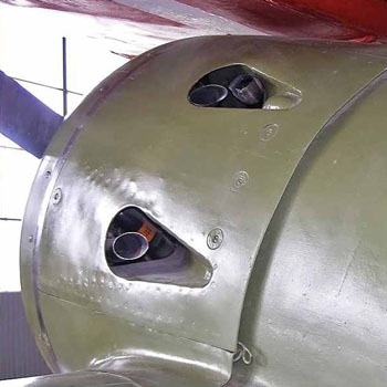
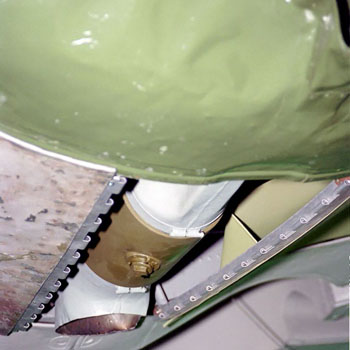
The vents for exhaust pipes on the left and right side of the cowling of the Type 5 in Chkalov museum.
The exhaust pipes protrude through the vent, one for each vent except for the upper left one that collects two vents, including the one of the upper cylinder.
The orange things vaguely visible inside are the bands on the admittance pipes behind the cylinders.
The shape of the slots of the Type 5 was more pointed than that of the following versions with M-25V emgine, as Type 10 or 17.
The bulges in the vents are probably for lodging the attachment points of the engine support strut to the wooden part of the fuselage, and disappeared on later versions that had shorter and more rounded vents.
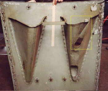
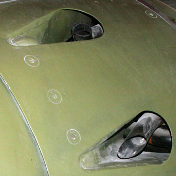
Photo of the inside of the right side cowling panel. The air vent ramps are evident.
The reason of the cut in one of them is probably to avoid interference with some internal thing.

The oil cooler was posed on the lower part, under the M-25V. It took air from the T-shaped intake on the front and expelled ot through a circular hole on the rear part of the lower cowling panel.
The image shows also two exhaust pipes in the typical position of Type 5 and early Type 10, that had four vents in their lower cowling panel, one for each pipe.
On later versions, the pipes and vents had a different configuration.
Some historical photos of early Type 10 and 17 show four vents and the circular opening for the air from the oil cooler.
Image from Istrebitel I-16 of Maslov
Left: photo of a late Type 10. The rounded shape of the exhaust vents is evident.
The division of the side panel ibto a main front element and a small rear one was introduced in late type 10 and 17 and preserved in the later models; it was to give easier access to the ammo boxes of the synchronized ShKAS on the top of the fuselage.
The circular hole for the oil refuelling is well visible on the top panel of the cowling.
The rectangular hatch open above the nose is for the fuel refuelling; this configuratopn was introduced with Type 10, while Type 5 had two separate caps.
Right:
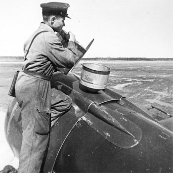
a technician is refuelling the oil tank.
The image gives an excellent view to the blisters of the synchronized ShKAS introduced with Type 10 and preserved in all later fighter versions.
Image from Istrebitel I-16 of Maslov
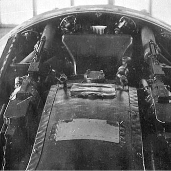
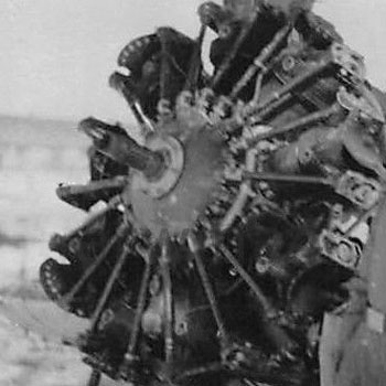
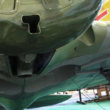
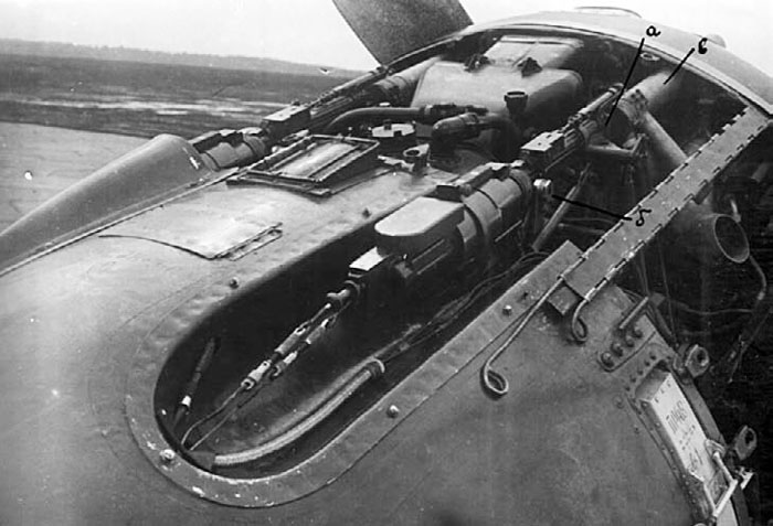
Image of the top of the nose with open cowling and mg blisters on a Type 17.
The image shows:
- the synchronized ShKAS in their recesses, entering in their blast tubes protruding from the front;
- the fuel refuelling hatch ( close, unpainted metal, common to Type 10 and all later versions);
- the rectangular hatch for the wing ShVAK loading; it was present on Type 17, 27 and 28, and in modified form on Type 29 for its UBS; it required a squared cut on the top panel of the cowling (not visible here);
- the oil refuelling cap, circular, common to all versions;
- the supercharger intake, aspiring air from behind of the top cylinder without its own intake open on the outside, typical of M-25, 25A and M-25V engined versions.
Image from Istrebitel I-16 of Maslov
The second image shows another M-25 from the front.
Another image of a Type 17, well recognizable for the wing ShVAK and for the typical, neary angular shape of the VFSh blades.
The side panels were removed, exposing the engine.
The image shows well:
- the dzud locks bases;
- the ammo boxes for the ShKAS just behind them, locked by pins;
- the hinge rods in nearly extracted position; their ring-shaped (or hook-shaped) end is recognizable.
Image from Istrebitel I-16 of Maslov
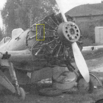
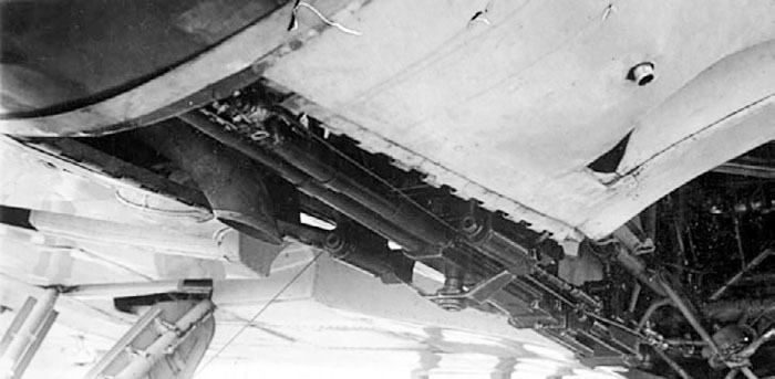
On Type 17, the possibility to retract the ski gear (that was fixed in previous versions) was introduced. This required a restyling of the lower plate of the cowling: the exhaust pipes were coupled into slots close to the wings to make room for recesses allowing the retracted skis to adhere to the fuselage.
This innovation was extended to the late Type 10, still in production at the end of 1938, and characterized all the successive fighter types except for Type 29.
Below left:
two images showing (vaguely) the sli recesses and the coupled exhaust pipes under the noses of late Type 10 and 17. Those recesses were opened on the inside of the cowling, and acted as air outlets too.
Below right:
when skis were not utilized, the recesses could have been partially closed by shaped and screwed plates, that left a slot open on their rear part for the air outcome from the engine. These small images (vaguely) show them.
About the UTI-4:
the early planes equipped with M-25 and M-25A, recognizablre for the lack of the oil cooler intake, had the same cowling of I-16 Type 5.
Early production UTI-4 with M-25V, recognizable for the presence of the air intake, had the same cowling sides and lower plates of Type 10, with individual vents for the exhaust pipes and (probably) the same circular outlet for the oil cooler air of early Type 10.
Late production UTI-4 with M-25V, as the one preserved in Vantaa in Finland, had their own version of the restyled lower panel of the cowling:
- coupled exhaust pipes (not visible in the photos aside because of the dismantled engine);
- the ventral vents seem to have had more divergent 'tails' than the fighter versions;
- thin slots for air outlet instead of the large retractable ski recesses, not required because they still used fixed ski gear;
- air outlet moved backwads, close to the end of the cowling (it's unclear if the corresponding panel had a circular hole or ended with an U cut)
- front plate with weak trapezoidal bumps between the vents, as those of M-62 and 63 engined fighter versions but more angular.
Top, left: details of the UTI-4 of Vantaa museum.
Right: detailof the nose of a Soviet UTI-4 in mid forties. Some details were different, and the slot was shaped as on Type 29.
Images from the web and from Scalemodels.ru
M-62 engined types
The M-62 engine was a Soviet copy of the Wright-Cyclone R-1820-G-5. It could also be considered similar to a M-25V with a two-speeds supercharger instead of the single speed one. The M-62 engine gave an output of 1000hp at take-off and 800 hp at an altitude of 2900 m,.It differed from the M-25 for having:
- a two speed supercharger based on the one used with the engine SR-1820-G103;
- a greater ribbed area on the cylinder heads;
- strenghtened pistons with lenghtened skirts;
- internal differences and modifications to the gas-distribution mechanism;
- it was feeded with 92 octane fuel instead of the 87 octane fuel of the previous engine
- a constant speed regulator for the use of a variable-pitch propeller VISh-6A or MV-1.
The engine was started from the electric starter RIM-U-24IR or manually by spinning the flywheel of the starter. The motor shaft rotated counterclockwise (viewed from the front).
Serial production was organized in 1937 at GAZ 19 in Perm with the productiuon of 25 engines, that had problems to the State tests; they were more or less resolved later, and the mass production started in March 1939, involving factories 19 and 24. This version was produced up to the second half of 1941, being stopped after 6884 ones.
Length, mm: 1328
Diameter, mm: 1380
Number of cylinders: 9
Displacement, l: 29.87
Compression ratio: 6.4
Dry weight, kg: 560
Take-off power, hp: 1000
Power near the ground, hp: 820
Power at an altitude of 1,500 m, hp: 840
Rotation speed, rpm: 2200
Turbocharging: impeller
In 1942, a modified version called ASh-62IR went into production, equipping important planes as Li-2 and An-2 and being produced even after the war. It was equipped with a planetary gearbox with a reduction ratio of 11:16.
http://xn--80aafy5bs.xn--p1ai/aviamuseum/dvigateli-i-vooruzhenie/aviamotorostroenie/aviamotory-sssr/porshnevye-i-dizelnye/porshnevoj-aviatsionnyj-dvigatel-m-62-ash-62/
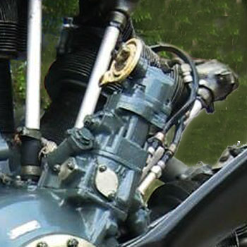
A visual detail that helps to distinguish the M-62 from the earlier M-25 and the later M-63 is the shape of the constant speed regulator on the front of the engine, at 1 o'clock. This was associated with an hydraulically-controlled system for the variation of the pitch of the prop blades.
To make room to the constant speed regulator, it was required a small flat extension of the front of the cowling at 1 o'clock. The system slightly protruded from the front vent at 1 o'clock.
Other visible differences were the enlarging of the oil cooler intake. that became trapezoidal with bent-in sides (or more rarely trapezoidal as on thios photo) and the addition of a triangular intake for the supercharger on the top of the front cooler.
The open cowling of an I-16 Type 29.
All what we see here should be common to all M-62 and M-63 engined versions, except for the raised hatch for the ammo loading of the UBS (Type 29) or for the wing ShKAS (Type 27-28), absent on Type 18 and 24.
We see:
- the ShKAS, their vanes and blast tubes;
- the ShKAS ammo boxes on the sides;
- the dzud lock bases and the hinges for the panels;
- the fuel refuelling hatch;
- the oil refuelling cap and oil pipes;
- the supercharger intake with a tunnel connecting the central part of it to the triangular air intake on the top of the cowling; this is a new thing compared to M-25V engined planes; this tunnel rarely appears on photos of planes in maintenance or on wrecks, so it seems that it was common use not to install it, perhaps for problems of overheating the top cylinder head.
- seems that the u-shaped plates conveying the cooling air around the cylinders to the outlet vents, seen on M-25 and 25V engined planes, were abandoned.
Image from Istrebitel I-16 of Maslov
The M-62 required a larger oil cooler than the M-25V; this required an extension to the central panel under the cowling, that became more curved and protruding, with an U-shaped opening on its rear; this characteristic is very well visible on profile images.
As late Type 10 and 17, the lower part of the cowling of the M-62 equipped I-16 (Type 18 and 27) was provided with coupled exhaust pipes and recesses for the retractable skis, that could be left open or, optionally, closed with removable D-shaped plates leaving a slot on their rear as an air outlet.
The new variable pitch propellers, VISh-6A or MV-1, were characterized by more rounded and bulbous spinners to lodge their balancing horns.
Page from a manual of AV-1 propeller.
The text seems to describe four types of AV-1:
N.01 and 02 had 2.8 m diameter and 250 mm chord; probably n.01 was for Type 18 and 27, and 02 for Type 24 and 28;
N.03 had 2.7 m diameter and 217 mm chord and balance horns of reduced size; its use is unclear, probably for refitting of some M-25V engined types;
N.04 had 2.7 m diameter and 250 mm chord, it was clearly for the Type 29.
Image from Scalemodels.ru
M-63 engined types
The M-63 was a further development of the M-62 engine. It was characterized by a compression ratio increased from 6.4 to 7.2., increased rpm and stronger supercharging and other internal modifications.
Its design began in 1937, and state tests were successfully completed in January 1939. Since 1939, the engine was mass-produced at GAZ 19 in Perm.
The engine was more powerful than the M-62, but less reliable, so its production ceased in December 1940/early 1941 after the production of 3087 M-63, while the M-62 production survived for transport planes even after the war's end.
Specifications:
Displacement, l: 29.87
Compression ratio: 7.2
Weight kg: 515
Take-off mode: power,1100 hp at 2300 rpm
Rated mode: power near the ground 930 hp; power at an altitude of 4500
m 900 hp
Above, left:
image of a somewhat uncomplete M-63 in the Navy Museum of Leningrad.
above, mid left; image of a M-63 mounted on an I-16 Type 24. The prop shaft is broken due to an accident.
Left:
A visual difference between M-62 and 63, that were very similar, was the larger speed regulator of different shape.
On this photo, it seems larger because of the perspective.
The propeller is not from an I-16.
Closer, left: an M-63 in mainenance, with well visible real proportions of the regulator.
While early production I-16 with M-63 (Type 24 and 28) could have had the same front plate of Type 18 and 27, on late production Type 24, 28 and 29 the position of the protrusion for the regulator at 1'o clock was slightly changed, and the closer vent had to be slightly reduced towards the propeller, becoming slightly smaller than the other vents.
The image shows also the balance horns of the MV-1 propeller (here shown with the frontal starter can dismounted).
Another small visual difference between the M-62/63 engined versions and the earlier M-25/25V engined ones was the presence of faintly visible oval protrusions between the vents.

Left:
This photo of the nose of a Type 24 gives a good idea of the versatility of the hinges: each panel could have been completely removed, extracting both rods of the hinges, or rotated on one hinge by extracting the rod from the other one.
Right:
drawing of the inside of the top panel of the cowling. The blister for the synchronized ShKAS are well recognizable.
Image from Scalemodels.ru.
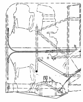
This diagram shows the position of the oil cooler under the engine on Type 18, 24, 27 and 28. The duct passing between the lower cylinders and the outlet aew recognizable.
The drawing shows also the cables to move the engine vent shutters, passing on the right of the engine.
Image from Scalemodels.ru.
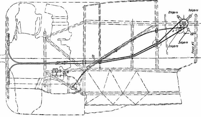
I-16 Type 29 was equipped with M-63 just as Type 24 and 28, but the installation of a UBS machine gun in central lower position (not shown on the diagram) obliged to move the oil cooler on the right side of 40°.
The image shows the cable to open and close a rotating shutter on the outcome of the oil cooler, and two cables for the shutters of the engine vents. All these were on the right side of the plane.
Image from Scalemodels.ru.
The oil cooler is visible through a removed panel. Its outlet was curved on the front, and flat on its rear.
Its presence allowed only one exhaust pipe to reach the right exhaust vent; the pipe of the lower.right cylinder had to be deviated on a ventral small vent in nearly central position (vaguely visible on the right of the photo)
The nearly vertical thin tube partially hidden by the wingroot is a waste shells expulsion pipe for the right ShKAS.
The photo shows also the ventral fairing for the UBS passing between the main wheel wells.
Image from Istrebitel I-16 of Maslov
The cowling of Type 29 had two different configurations in the oil cooler area, that had to be moved to make room for the UBS machine gun in the central position.
The earlier one had an intake of trapezoidal with bent-inside sides shape, more or less similar of that of earlier M-62/63 types, but moved of 40° on the right ; its tunnel passed between two cylinders.
The outlet was on the right side, had a rounded front and square rear. In front of it, a drop-shaped blister and a very small rectangular hatch ( not visible on these photos).
The outlet came out from a bell-shaped extension of the venting slot (otherwise similar to that of late UTI-4).
The propeller of Type 29 was a modified MV-1 whose blades were shortened to a diameter of 2.7 m instead of the usual 2.8 m of all other types; this was made to preserve the ground clearance after a shortening of the landing gear. The blades were enlarged and rounded in their outer part to preserve the thrust.
The later variant of Type 29 had its intake replaced by an oval hole between two vents. The hole was repeated on the shutter, so, when this was in closed position, we see two oval holes.
The outlet was slightly moved (forward and on the right) closer to the exhaust pipe.
The cut around the outlet had a different shape, more angular, then it merged with the wide slot similar to that of late type UTI-4.
The shape of the outlet was strange: it seems narrower on its back, but it is possible that this was an optical illusion due to a non-planar cut of its inner/rear edge.
The drop-shaped blister and the small rectangular hatch were deleted.
This image, with the blister of the UBS removed, shows well the weapon and the lower exhaust pipe, coming out under the engine.
The image shows also the thin circular outlet for the waste shells of the left ShKAS.
The venting slot that took the place of the ski recesses is visible. It is different from the one on the right side because it hasn't to let the oil cooler outlet pass. Its shape was more or less similar to that of late UTI-4 M-25V, with a bell-shaped front and a straihght rear.
In absence of contrary proof, we can suppose that it was the same both on early Type 29, both on late ones.
Image from Istrebitel I-16 of Maslov