|
by Massimo Tessitori |
|
|
|
|
|
|
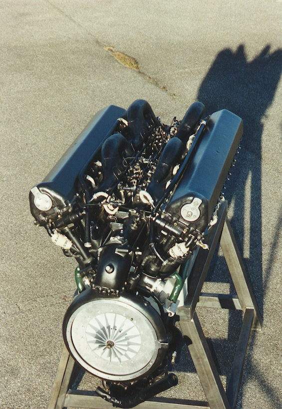
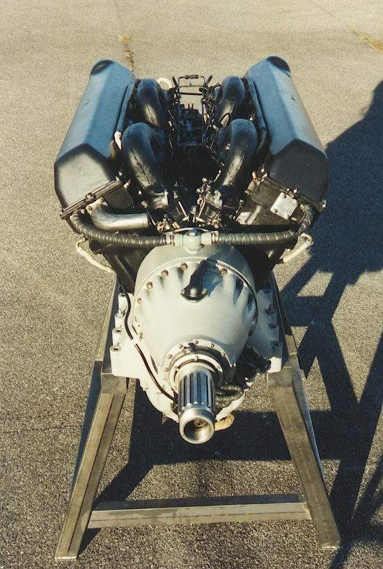
Here are the rear and front views of an engine AM-42 restored at the Deutsche Museum of Munchen. The covering plate of the compressor and the inlet pipe looks missing.
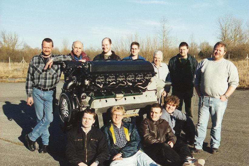
Here is the team that restored the engine.
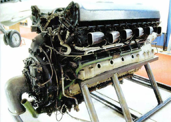
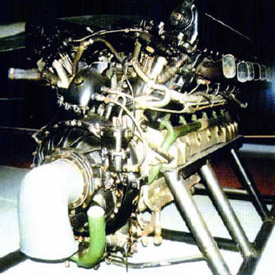
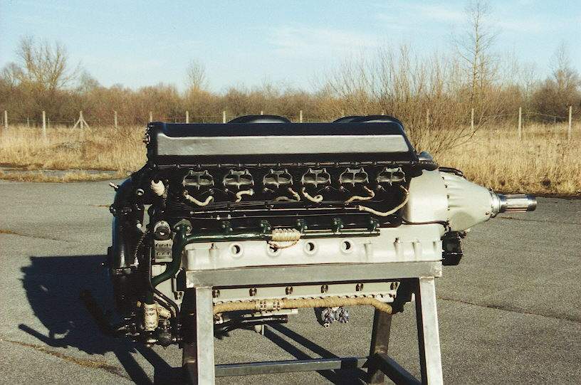
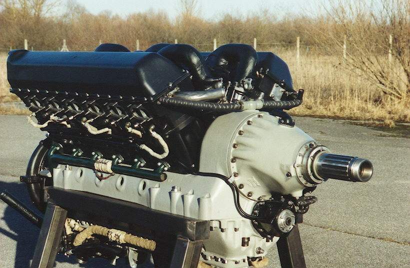
Here are two images of the engine in Prague-Kbely museum. Note that
this engine is complete of exhaust pipes, cover of compressor, air pressure
control valves and air inlet duct. The green pipe is for coolant.
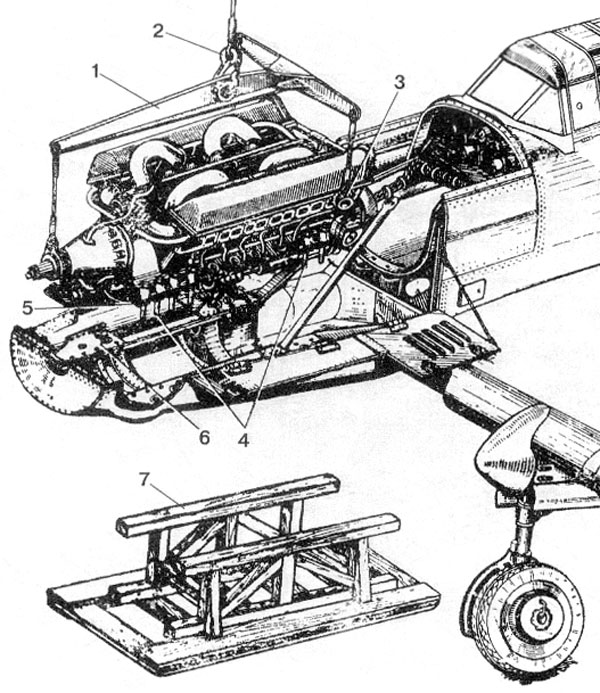 |
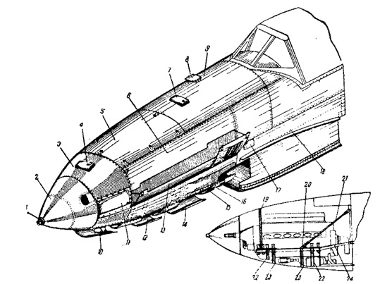
Here are shown instructions on how to remove and lift the engine from the plane, and support it on the ground. |
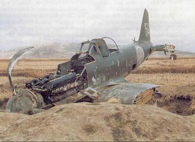 |
This wartime photocolor of an Il-10 downed in Korea shows some details
of the engine, while fuel tanks and many other important pieces are missing.
Note the dark grey color (A-14) of internal surfaces and the dark brown headrest.. |
Engine maintanance doors
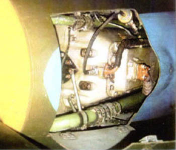 |
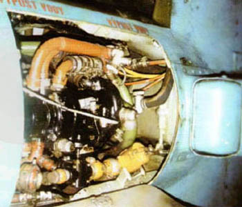
Some images of open access hatches on the armoured nose.
The first one under the nose shows the lower part of reduction gear and of oil cup. Green pipes are for coolre, brown ones are for oil. |
|
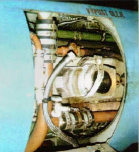 |
The second panel gives access to the electrical generator under the engine, that is visible on the first photo, but is lacking in the second on, where we see only its support and the shaft from the oil pump. | |
 |
The third access shows the oil circulation pump, in black, scarcely visible under the engine; brown oil pipes are connected to it, while yellow pipes are for fuel. | |
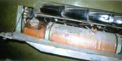 |
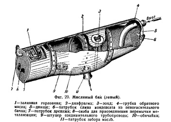
The brown structure visible under the exhaust pipes is a 47 l oil tank. On the right of the first photo, the man fuel tank is visible. |
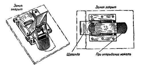
A detail of fast locks on the left side. Hinges on the right side protruded
on the surface of the plane.
Coolers intakes and outlets
 |
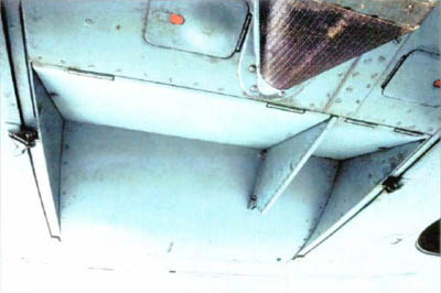
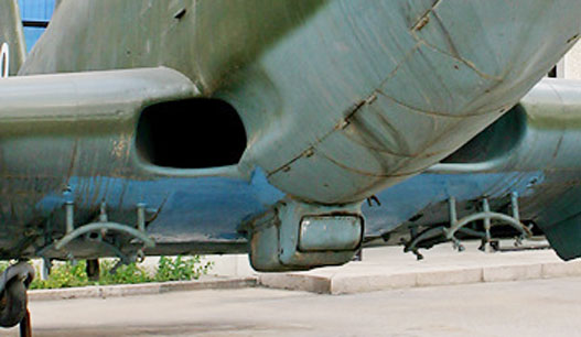
Aside: the wingroots intakes for the coolers.
The right intake leds to the coolant cooler, while the left one is divided by a wall, and goes partly to the coolant cooler, partly to the oil cooler. I dont't know what is the U-shaped plate, not always present on Il-10s. |
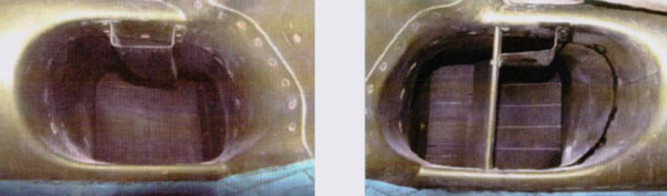
| Below: the coolers outlet with both flaps closed, seen from the front
below. Note the thin wall separing them. The opening of flaps in independant
each other.
Right: the oil flap open, seen from the rear. The oil cooler and the opening brace are visible.
|
 |
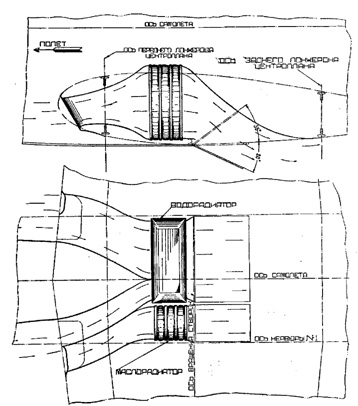 |
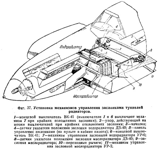
Above, images of the air tunnels for coolant and oil coolers, from the
wingroots to the outlets. Note the flaps opening angle and the position
of openingbraces. The reason of the division of the left intake is clear.
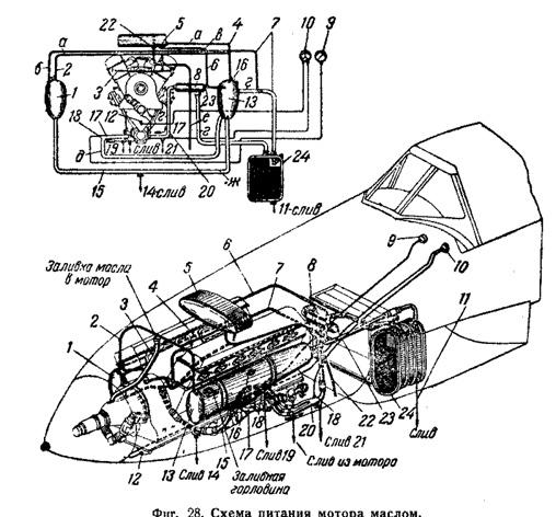
Oil circuit
Components of oil circuit were fortemost painted brown.
Cooler circuit
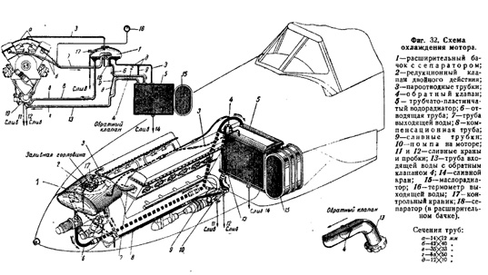
Components of cooler circuit were forthemost painted bright green.
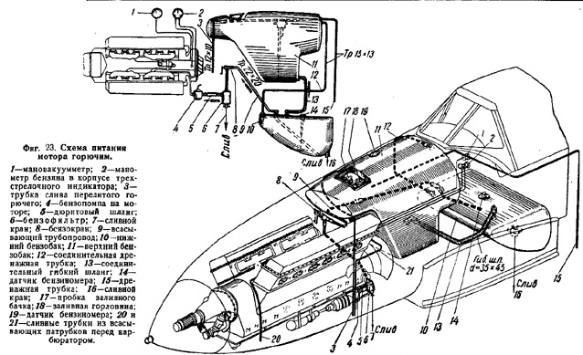
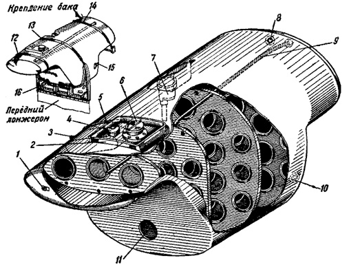
Fuel tanks
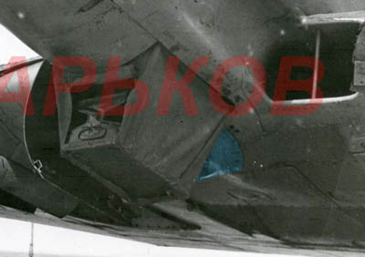
Intake of supercharger
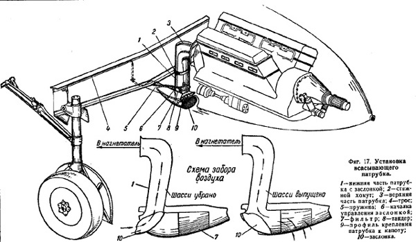
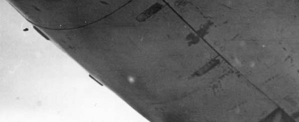
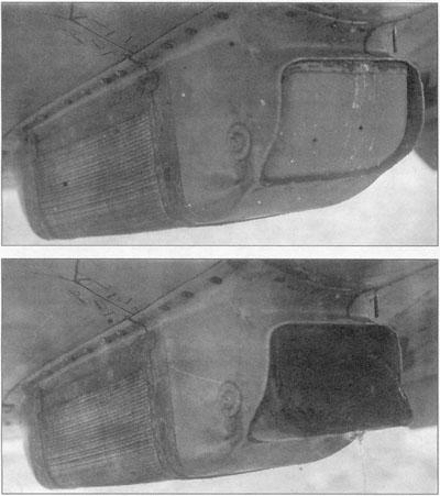
Very early Il-10s, in late 1944-start of 1945, weren't provided of dust filter. On April 30, 1945, dust filters entered production, and existing planes were refitted with such filters in a modified version that was mountable under field conditions. Photos show that very early Il-10s have an intake whose rear profile is curved (Spitfire-like), but unfortunately none image is clear enough to see if there was a shutter on the front, as drawn on the schemes aside, or the inlet was free, as on the larger drawing above them. |
Photos above show an attempt to put in evidence, in blue, what is visible of this intake on the available images. In the first photo, the intake is obscured by a ground device possibly related with the maintenance of the oil pump. |
 |
This is the definitive filter of Il-10/B-33: the frontal air intake is closed when the landing gear is extended, and opens in the air. When the shutter is closed, air enters through the grille on the central and rear part and is filtered. |